Main and standby power supply switching device and method

A technology of main and backup power supply and switching device, applied in the field of electronics, can solve the problem of high cost and achieve the effect of reducing cost

Pending Publication Date: 2022-03-29
浙江华锐捷技术有限公司
View PDF0 Cites 0 Cited by
  • Summary
  • Abstract
  • Description
  • Claims
  • Application Information

AI Technical Summary

Benefits of technology

This technology allows for efficient use of spare battery supplies when there are only one available from primary sources like an AC line (AC) instead of multiple batteries). It achieves this through comparing two different voltages with each other. By doing that it can save money compared to having separate circuits for both types of energy storage devices. Additionally, if any problem arises during operation, another circuit called the backup system will be used without interrupting its function until needed again. Overall, these technical improvements make the process more economically viable than traditional methods.

Problems solved by technology

This patented technical problem addressed in this patents relates to improving the efficiency and reliability of two separate systems for supplying electricity from vehicles' batteries during certain conditions such as when they are turned off while waiting outside traffic lights without losing their charge.

Method used


Image

  • Main and standby power supply switching device and method
  • Main and standby power supply switching device and method
  • Main and standby power supply switching device and method

Examples


Embodiment Construction

[0029] Embodiments of the present invention will be described in detail below with reference to the drawings and in combination with the embodiments.

[0030] It should be noted that the terms "first" and "second" in the description and claims of the present invention and the above drawings are used to distinguish similar objects, but not necessarily used to describe a specific sequence or sequence.

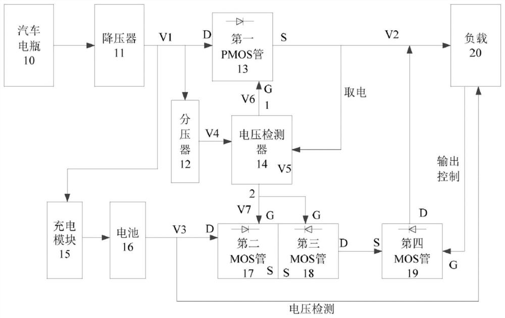
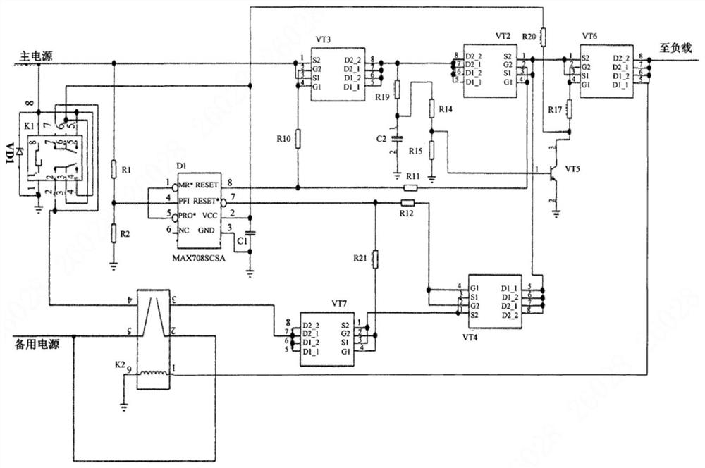
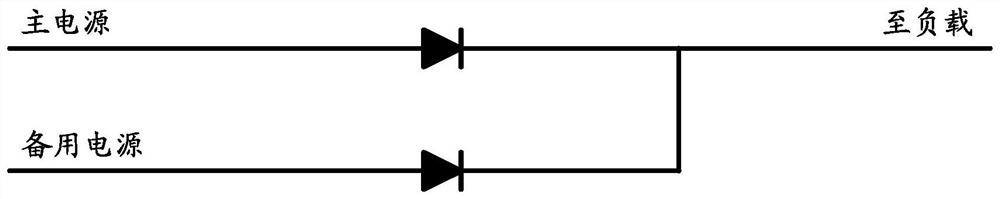
[0031] In the related technology, there is a special main and standby power switching control chip to control the power transistor to realize the switching of the main and standby power supply. figure 1 It is an example of the main and standby power supply switching scheme in the related technology Figure 1 , the main disadvantage of this scheme is that the cost of the dedicated main and standby power switching control chip is relatively high; and the main and standby power switching is realized by using the power monitoring chip to control the power transistor, such as figure 2


PUM


Abstract

The embodiment of the invention provides a main and standby power supply switching device and method.The device comprises a voltage comparison module, a switching control module, a first controllable switch module, a second controllable switch module and a hysteresis control module, and the voltage comparison module is used for comparing the voltage of a main power supply and the voltage of a standby power supply; the first controllable switch module is connected with a main power supply and a load, and the second controllable switch module is connected with a standby power supply and a load; the switching control module is connected with the voltage comparison module; the switching control module is used for controlling the on-off of the first controllable switch module and the second controllable switch module based on the comparison result of the voltage comparison module; the hysteresis control module is connected with the switching control module and the voltage comparison module, and the switching control module carries out hysteresis control on the voltage comparison module through the hysteresis control module. According to the invention, the problem of high cost of a main and standby power supply switching scheme in the prior art is solved, and the effect of reducing the cost is achieved.

Description


Claims


Application Information

Patent Timeline
Owner 浙江华锐捷技术有限公司
Why Eureka
Try Eureka