System and method for monitoring material fatigue

A technique of fatigue and fatigue damage, applied in the direction of testing material strength, analyzing material, measuring force, etc. by applying stable bending force, which can solve problems such as high cost and production stoppage

Pending Publication Date: 2022-04-01
拉普兰塔拉登理工大学
View PDF0 Cites 0 Cited by
  • Summary
  • Abstract
  • Description
  • Claims
  • Application Information

AI Technical Summary

Benefits of technology

This patented technology allows us to monitor how well things work over their lifetime by calculating the accumulated effect on them from multiple sources such as temperature changes caused by factors like vibration or shocks. By comparing these results against reference data collected beforehand, we aimed at identifying areas where there was more likely failure than usual.

Problems solved by technology

This technical problem addressed by this patents relates to how to monitor if an object has been exposed to severe loads over time without causing any visible defects on its surface due to excessive strains caused by repeated cycles of tensile deformation under heavy pressure.

Method used


Image

  • System and method for monitoring material fatigue
  • System and method for monitoring material fatigue
  • System and method for monitoring material fatigue

Examples


Embodiment Construction

[0028] The specific examples provided in the following description should not be construed to limit the scope and / or applicability of the appended claims. The list of examples and groups provided in the specification are not exhaustive unless expressly stated otherwise.

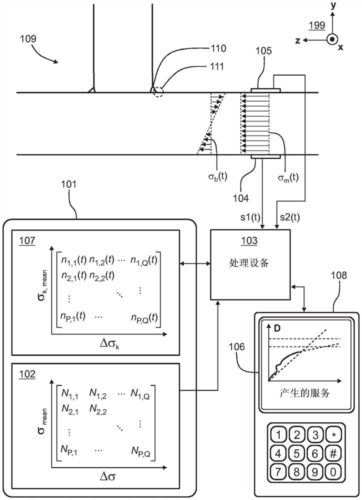
[0029] figure 1 A functional block diagram of a system for monitoring fatigue of an exemplary mechanical structure 109 is shown in accordance with an exemplary and non-limiting embodiment. exist figure 1 In the exemplary case shown, the mechanical structure 109 includes a welded T-joint 110 and fatigue is monitored at an observation point 111 of the mechanical structure 109 . It should be noted that the mechanical structure 109 is shown for illustrative purposes only, and figure 1 The system shown is applicable to many different mechanical structures to be monitored.

[0030] The system comprises a storage device 101 which stores a database 102 containing predetermined response values ​​N 1,1 ,...,N P,Q


PUM


Abstract

A system for monitoring fatigue of a mechanical structure includes a memory (101) that stores response values, each response value relating to one of predetermined stress ranges and one of predetermined average stresses. Each response value represents an upper limit of the number of stress cycles at a predetermined observation point of the mechanical structure in a case where the cycles have a stress range and an average stress associated with the response values. The system comprises a processing device (103) for updating, for each response value, a stress history value representing a number of cycles occurring in a time trend of stress and having a stress range and an average stress associated with the response value. And updating the fatigue damage sum based on the response value and the stress history value. The sum of fatigue damage represents cumulative fatigue damage of the mechanical structure and may be used for real-time fatigue monitoring.

Description


Claims


Application Information

Patent Timeline
Owner 拉普兰塔拉登理工大学
Why Eureka
Try Eureka