Sewage drainage pipeline system

A technology for drainage pipes and sewage, applied in separation methods, filtration separation, chemical instruments and methods, etc., can solve problems such as hidden safety hazards, blockage of drainage pipes, etc., and achieve the effect of reducing maintenance costs, reducing impurities, and improving cleaning effects.

Inactive Publication Date: 2022-05-06
苏州六度设计研究院有限公司
View PDF1 Cites 0 Cited by
  • Summary
  • Abstract
  • Description
  • Claims
  • Application Information

AI Technical Summary

Benefits of technology

The technical features described are improvements for draining systems used with wastewater collection or disposal facilities such as septic tunnels. These improved systems use specialized equipment called transportation meshes made up of various materials like metal rods, rubber bands, wires, cables, etc., along their length to create channels through which liquids flow smoothly without getting stuck inside them due to gravity. This allows any impurity particles found within these structures to move freely throughout it before being collected downstream. Additionally, there may also include an apparatus called a damper plate placed at one end near where the liquid flows outlet pipe. When this device detects certain conditions (such as excessive rain) indicating possible issues), they trigger a signal sending control mechanisms to stop moving objects around the structure's walls until maintenance work takes place again. Overall, these modifications improve the efficiency and security of the waste management facility.

Problems solved by technology

The technical problem addressed by this patented innovation relates to improving the efficiency and effectiveness of wastewater disposal systems used during cleaning up after construction projects such as residential homes. Current methods involve removing debris from septic tanks before draining them downstream without effectively treating any harmful substances associated with these processes.

Method used


Image

  • Sewage drainage pipeline system
  • Sewage drainage pipeline system

Examples


Embodiment Construction

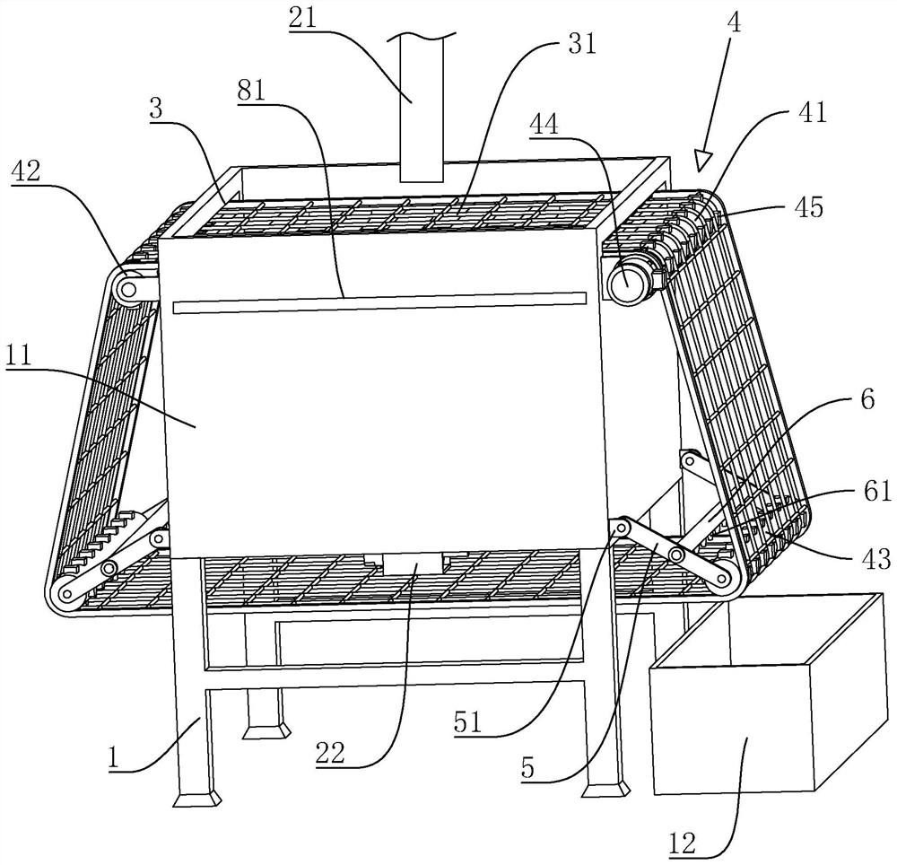
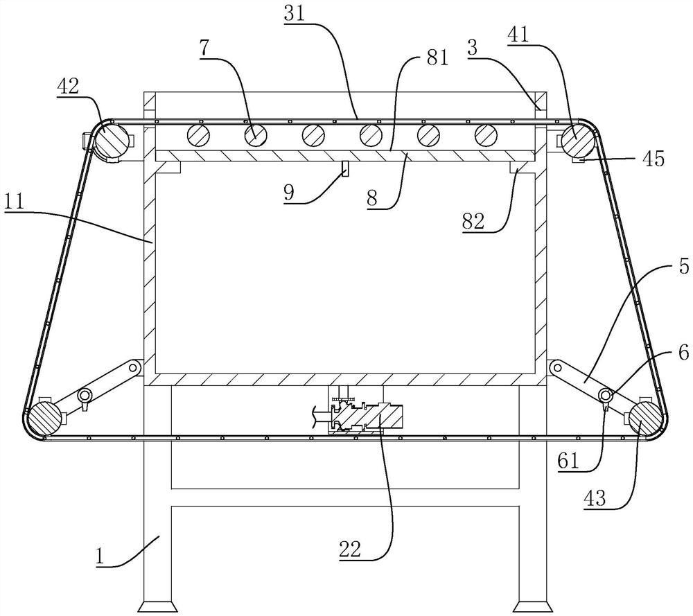
[0034] The following is attached Figure 1-2 The application is described in further detail.

[0035] The embodiment of the present application discloses a sewage drainage pipeline system. refer to figure 1 and figure 2, which includes a bracket 1, a water storage tank 11, a water inlet pipe 21 and a drainage pipe device 22, the water inlet pipe 21 is used to collect domestic sewage, and the water inlet pipe 21 is located above the water storage tank 11. The bracket 1 is fixedly arranged at the four top corners of the bottom wall of the water storage tank 11, the bracket 1 is used to support the water storage tank 11, the sewage flows into the water storage tank 11 through the water inlet pipe 21, and the drainage pipe device 22 is connected to the At the bottom of the water storage tank 11 , the drainage pipe device 22 can discharge the sewage collected in the water storage tank 11 .

[0036] refer to figure 1 and figure 2 A group of transport holes 3 are provided symmet


PUM


Abstract

The invention relates to a sewage drainage pipeline system, and relates to the technical field of sewage treatment.The sewage drainage pipeline system comprises a support, a water storage tank, a water inlet pipeline and a drainage pipeline device, the water inlet pipeline is located above the water storage tank, the drainage pipeline device is connected to the bottom end of the water storage tank, and the support is fixedly arranged on the bottom wall of the water storage tank; a group of conveying holes are symmetrically formed in the inner side wall of the water storage tank, a conveying net belt is arranged in the conveying holes in a penetrating mode, a driving mechanism is arranged on the outer side wall of the water storage tank and used for driving the conveying net belt to conduct transmission in the conveying holes, and a recycling box is arranged outside the water storage tank and located below the conveying net belt. The device has the effects of reducing the phenomenon that the drainage pipeline is blocked by impurities, reducing the potential safety hazard of the system and reducing the maintenance cost.

Description


Claims


Application Information

Patent Timeline
Owner 苏州六度设计研究院有限公司
Why Eureka
Try Eureka