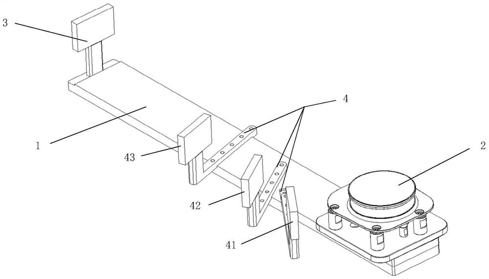
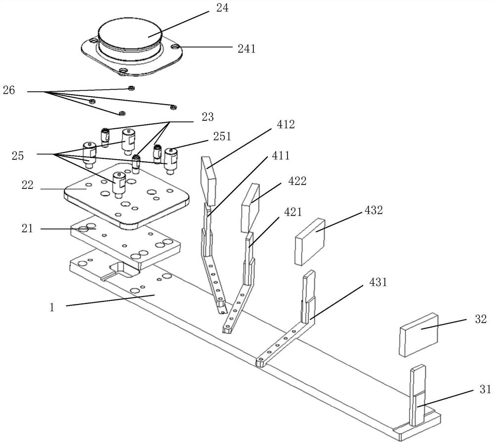
Laser radar test fixture

A technology of laser radar and test fixture, which is applied to radio wave measurement systems, instruments, etc., can solve the problem of not being able to test the accuracy of laser radar at the same time

Pending Publication Date: 2022-05-17
珠海视熙科技有限公司
View PDF8 Cites 0 Cited by
  • Summary
  • Abstract
  • Description
  • Claims
  • Application Information

AI Technical Summary

Benefits of technology

This patented device consists of two parts - an upper plate with several targets attached thereto for testing purposes. One objective lens focuses light onto these targets while another adjusts their positioning based upon factors like altitude or wind speed. By measuring both parameters simultaneously during rotation around its axis, this technology allows accurate measurements over large areas without requiring multiple devices.

Problems solved by technology

This patented technical problem addressed in this patents relates to improving the precision with which measurements made by Lidars are used for various applications such as robotics or autonomous vehicles (AV). Specifically, current methods require multiple steps involving reassembly and adjustment of targets during measurement processes, making them difficult to perform simultanously on different locations within the field undergoing analysis.

Method used


Image

  • Laser radar test fixture
  • Laser radar test fixture

Examples


Embodiment Construction

[0038] In this embodiment of the application, the terms "upper", "lower", "left", "right", "front", "rear", "top", "bottom", "inner", "outer", "middle" ", "vertical", "horizontal", "horizontal", "longitudinal" and other indicated orientations or positional relationships are based on the orientations or positional relationships shown in the drawings, and are only used to illustrate the relative The positional relationship does not specifically limit the specific installation orientation of each component or component.

[0039] Moreover, some of the above terms may be used to indicate other meanings besides orientation or positional relationship, for example, the term "upper" may also be used to indicate a certain attachment relationship or connection relationship in some cases. Those skilled in the art can understand the specific meanings of these terms in this application according to specific situations.

[0040] Furthermore, the terms "installed", "disposed", "provided", "conn


PUM


Abstract

The embodiment of the invention discloses a laser radar test fixture which is used for testing the precision of a laser radar at different distances at the same time. The device comprises a bottom plate, a fixing part, a first target assembly and at least one second target assembly. The bottom plate is fixedly connected with the fixing part; the fixing part is used for fixing the laser radar; the first target assembly is fixedly connected with the bottom plate; the second target assembly is connected with the bottom plate; the distance from the first target assembly to the fixing part is different from the distance from each second target assembly to the fixing part, and the distance from each second target assembly to the fixing part is different.

Description


Claims


Application Information

Patent Timeline
Owner 珠海视熙科技有限公司
Why Eureka
Try Eureka