Optical microscopic observation device and method
An optical microscope and observation device technology, applied in optics, microscopes, optical components, etc., can solve the problem of inability to etch the optical observation of the channel, achieve the effect of finely controlling the irradiation angle and brightness, and reducing the degradation of imaging quality
- Summary
- Abstract
- Description
- Claims
- Application Information
AI Technical Summary
Benefits of technology
Problems solved by technology
Method used
Image

Examples
Embodiment approach 1
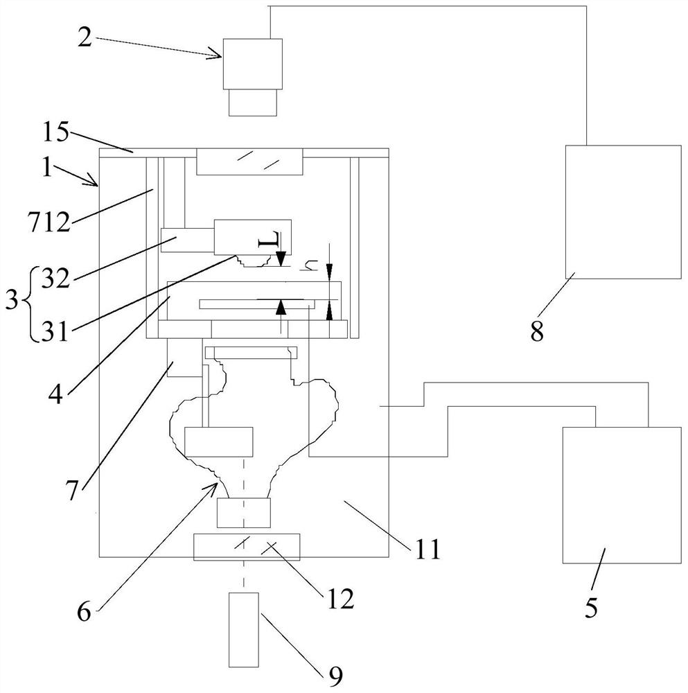
[0066] like figure 2 As shown, the present invention provides an optical microscopic observation device, which includes an autoclave 1, an image acquisition device 2, an observation device 3, a glass visual model 4 and a displacement device 5, and the autoclave 1 has a confining pressure cavity 11, The image acquisition device 2 and the displacement device 5 are arranged outside the autoclave 1, and the observation device 3 and the glass visual model 4 are arranged in the confining pressure cavity 11. 4. Apply confining pressure to simulate the high pressure environment of the oil reservoir. The glass visual model 4 is connected to the displacement equipment 5. The glass visual model 4 has etched channels. To simulate the water flooding process in a high-pressure environment, the autoclave 1 is provided with opposite light source windows 12 and observation windows 13, and the light of the light source 9 enters the autoclave 1 through the light source window 12, for example, the
Embodiment approach 2
[0089] The present invention also provides an optical microscopic observation method, which uses an optical microscopic observation device to perform a microscopic visualization experiment. The optical microscopic observation device in this embodiment has the same structure, working principle and beneficial effect as the first embodiment. No further description; the optical microscopic observation method of the present invention comprises the following steps:
[0090] Step S1: injecting the confining pressure fluid into the confining pressure cavity 11 for providing the confining pressure to the glass visual model 4;
[0091] Step S2: evacuating the glass visual model 4;
[0092] Step S3: inject oil into the pores of the glass visual model 4 through the displacement device 5, and make the oil pressure in the pores of the glass visual model 4 and the confining pressure in the confining pressure cavity 11 keep a predetermined pressure difference and increase synchronously, Until t
PUM
| Property | Measurement | Unit |
|---|---|---|
| Thickness | aaaaa | aaaaa |
Abstract
Description
Claims
Application Information
 - R&D Engineer
- R&D Manager
- IP Professional
- Industry Leading Data Capabilities
- Powerful AI technology
- Patent DNA Extraction
Browse by: Latest US Patents, China's latest patents, Technical Efficacy Thesaurus, Application Domain, Technology Topic.
© 2024 PatSnap. All rights reserved.Legal|Privacy policy|Modern Slavery Act Transparency Statement|Sitemap