Tactile presentation panel, tactile presentation touch panel, tactile presentation touch display, and tactile presentation knob

A touch panel and haptic technology, applied in the field of tactile display touch display and tactile display knob, can solve the problems of low cost, incapable of large area, unsuitable for frame embedding, etc.

Pending Publication Date: 2022-07-08
MITSUBISHI ELECTRIC CORP
View PDF2 Cites 0 Cited by
  • Summary
  • Abstract
  • Description
  • Claims
  • Application Information

AI Technical Summary

Benefits of technology

This new technology has its benefits that are explained below for better understanding by referring to specific examples or figures drawn up on this figure-making process.

Problems solved by technology

This patent describes various technical features related to improving the functionality and usability of touch screens found in vehicles and consumer electronics products. One key issue addressed is how to ensure reliable operation despite environmental factors such as rainwater immersion, dust protection, temperature variations, etc., especially under conditions where visibility becomes poor. Additionally, the use of auditory displays made up of multiple layers allows users to experience both visual and audio experiences simultaneously.

Method used


Image

  • Tactile presentation panel, tactile presentation touch panel, tactile presentation touch display, and tactile presentation knob
  • Tactile presentation panel, tactile presentation touch panel, tactile presentation touch display, and tactile presentation knob
  • Tactile presentation panel, tactile presentation touch panel, tactile presentation touch display, and tactile presentation knob

Examples


Embodiment approach 2

[0181] Figure 30 It is an impression diagram in the case of using the tactile presentation knob 3 on the tactile presentation touch panel 400 set up obliquely or vertically. Figure 31 It is a schematic diagram showing the configuration of the rotating portion 4 a in the case where the tactile presentation knob 3 is used on the tactile presentation touch panel 400 set up obliquely or vertically. Figure 32 It is a schematic diagram showing the configuration of the fixing portion 5 a in the case where the tactile presentation knob 3 is used on the tactile presentation touch panel 400 set up obliquely or vertically. Figure 33 It is a schematic diagram showing the configuration of the fixing table 13 a in the case where the tactile presentation knob 3 is used on the tactile presentation touch panel 400 set up obliquely or vertically.

[0182]When using the tactile rendering knob 3 on the tactile rendering touch panel 400 that is not horizontally, obliquely or vertically set up, i

Embodiment approach 5

[0197] also available in Figure 12 The side opposite to the operating surface of the tactile presentation panel 100 shown is configured as Figure 36 The touch panel shown in segmented construction. Even in this case, configure the Figure 36 The detection electrodes and excitation electrodes in the region of A can be as Figure 37 , 38 shape. In addition, the shapes of the detection electrodes and the excitation electrodes are not limited to Figure 37 , 38 It is only necessary to have a structure in which the mutual capacitance in the same region is larger than the mutual capacitance with the electrodes between the regions of the detection electrode and the excitation electrode that are different in adjacent structures. Specifically, the distance between the detection electrode and the excitation electrode in the same region may be narrower than that between the detection electrode or the excitation electrode in different regions. As a result, the influence of the capac


PUM


Abstract

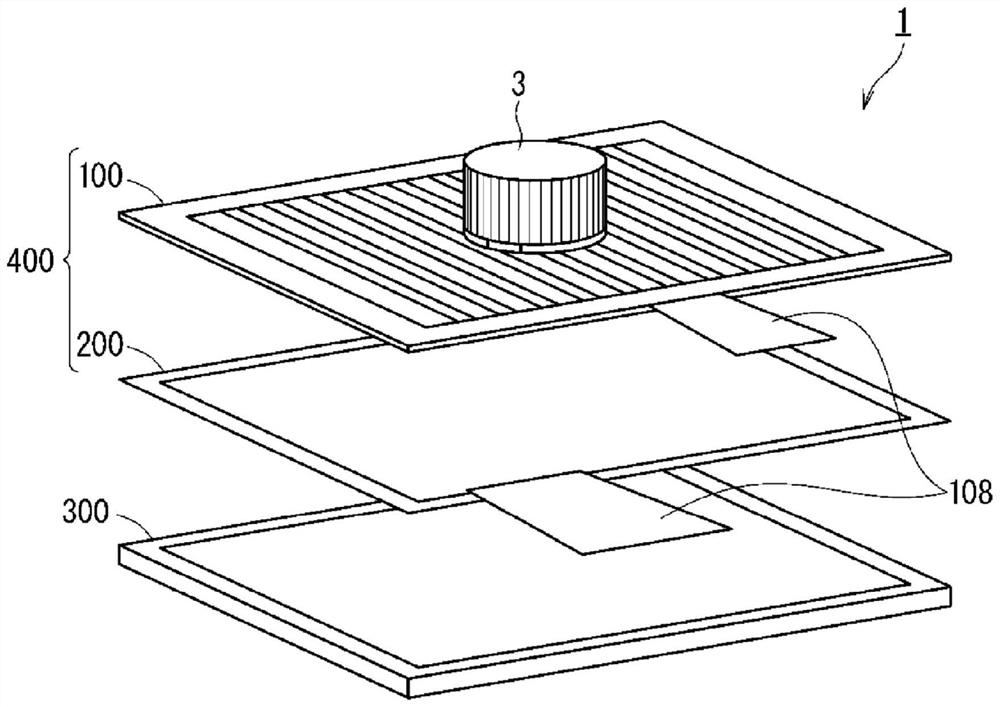
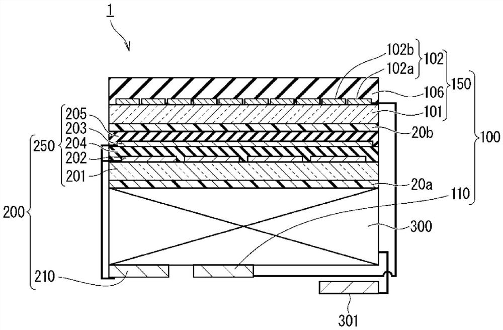
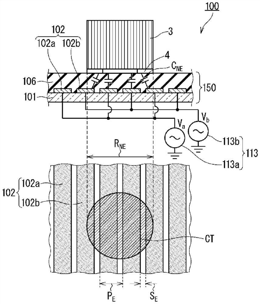
The purpose of the present invention is to provide a tactile sensation presentation panel, a tactile sensation presentation touch panel, a tactile sensation presentation touch display, and a tactile sensation presentation knob capable of imparting an appropriate tactile sensation to a user. A haptic presentation panel according to the present invention is provided with: a haptic presentation voltage generation circuit (113) that generates a voltage signal having a first frequency that is applied to at least one first electrode (102a) located in at least a partial region of an operation surface of the haptic presentation panel; a voltage signal generating unit (102) that generates a voltage signal having a second frequency different from the first frequency and applied to at least one second electrode (102b) located in at least a partial region of the operation surface of the tactile presentation panel; a charge discharge unit (115) that is connected to the tactile electrode and discharges the charge accumulated in the conductive elastic unit (6); and a touch detection circuit (210) that detects that a user touches the tactile presentation knob (3).

Description


Claims


Application Information

Patent Timeline
Owner MITSUBISHI ELECTRIC CORP
Why Eureka
Try Eureka