Asynchronous motor

A technology for asynchronous motors and stators, applied to asynchronous induction motors, electrical components, electromechanical devices, etc., can solve the problems of motor efficiency limitation, insignificant efficiency improvement, large reactive power loss, etc., and achieve the effect of improving motor efficiency

Inactive Publication Date: 2004-04-28
韩天鹏
View PDF0 Cites 0 Cited by
  • Summary
  • Abstract
  • Description
  • Claims
  • Application Information

AI Technical Summary

Benefits of technology

This patented technology allows for more electrical energy into certain parts of its system without making them bigger than necessary due to changes made during operation. By doing this it improves their performance compared with traditional methods like induction machines while also allowing other components within these systems to work better together.

Problems solved by technology

There exist different types of synchronous machines that use multiple phase windings in their design: squirreclable (SQ) type machine where all phases have one coil inside them; winding type machine called WRM (Winding Resonance Motor), where there's only one single wire wrapped around every turn of its own axis instead of being surrounded by another spiral shaped conductive material like iron). These designs can lead to significant energy losses due to induced electrical currents caused by interaction between these windings during operation.

Method used


Image

  • Asynchronous motor
  • Asynchronous motor
  • Asynchronous motor

Examples


Embodiment Construction

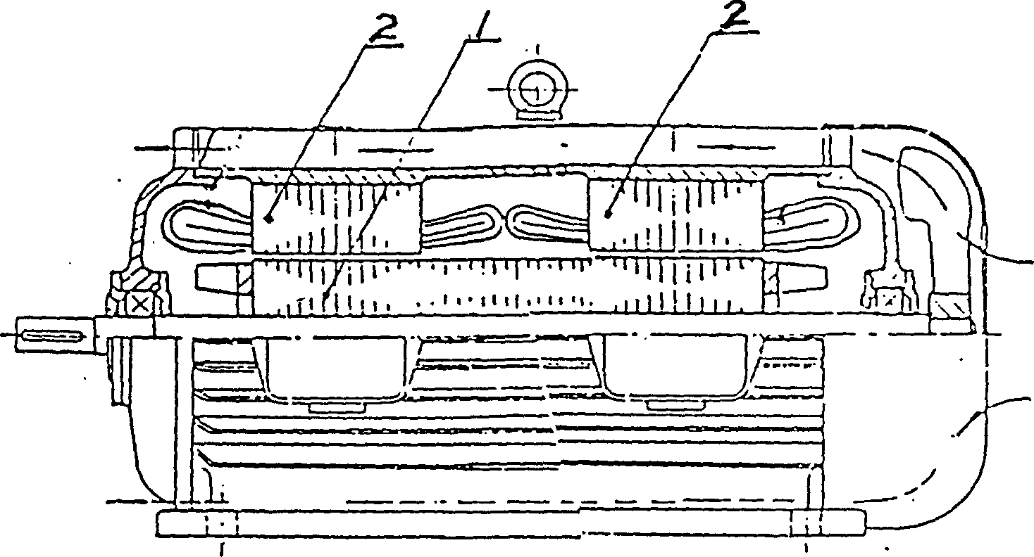
[0020] Such as figure 1 In the illustrated embodiment, the motor includes a rotor core and two stator cores.

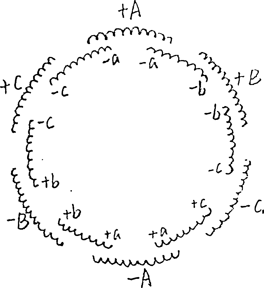
[0021] Such as figure 2 In the straight-line structure schematic diagram of a set of main windings and auxiliary windings shown, the main windings and auxiliary windings are laid across phases.

[0022] Such as Figure 5 The example shown is in the figure 1 On the basis of the structure, the two stator cores are divided into a fixed core 4 and a rotating core 5, the rotation angle can be adjusted by the worm wheel 6 and the worm 7, and the rotating core can be fixed at the required relative angle position by the positioning screw 8 , so that the two stator cores are staggered by an electrical angle. The structure of the set screw 8 is as Figure 6 Shown, ball 9 is installed at its bottom, and it can cooperate with the locating groove on the rotating iron core.

[0023] Such as Figure 7 Shown is a schematic diagram of a broken-line winding, a set of main winding


PUM


Abstract

The present invention relates to the improvement of motor structure. The present invention features that there are insulating layer between the strip or coil and iron of motor rotor, and one or two stator iron cores with at least two embedded triphase windings outside the rotor. Of the triphase windings, one is connected to power supply and named main winding and the other(s) with equal phase or different phase end connected parallelly or serially to form a loop is not connected to power supply and named subsidiary winding. The present invention has the merit of that the increased subsidiary winding or two stator iron cores and changed stator phase angle prduces in the rotor an additional torque to raise motor efficiency obviously.

Description


Claims


Application Information

Patent Timeline
Owner 韩天鹏
Why Eureka
Try Eureka