Thermal expansion riveting press-fit equipment

A technology of riveting and equipment, which is applied in the field of riveting and pressing, can solve the problems of low efficiency and achieve the effect of improving efficiency

Pending Publication Date: 2022-08-05
广州安博新能源科技有限公司
View PDF1 Cites 0 Cited by
  • Summary
  • Abstract
  • Description
  • Claims
  • Application Information

AI Technical Summary

Benefits of technology

This technology helps improve heating and cool down processes for joining materials together more efficiently than traditional methods like welds or glue guns.

Problems solved by technology

This patented technical problem addressed in this patents relates to improving the efficient use of pulling rivets during riveting processes due to their high elongation properties.

Method used


Image

  • Thermal expansion riveting press-fit equipment
  • Thermal expansion riveting press-fit equipment
  • Thermal expansion riveting press-fit equipment

Examples


Embodiment Construction

[0038] In order to facilitate understanding of the present invention, the present invention will be described more fully hereinafter with reference to the related drawings.

[0039] It should be noted that when an element is referred to as being "connected" to another element, it can be directly connected to and integrated with the other element, or intervening elements may also be present. The terms "installed," "one end," "the other end," and similar expressions used herein are for illustrative purposes only.

[0040] Unless otherwise defined, all technical and scientific terms used herein have the same meaning as commonly understood by one of ordinary skill in the art. The terminology used in the specification herein is for the purpose of describing specific embodiments only and is not intended to limit the present invention. As used herein, the term "and / or" includes any and all combinations of one or more of the associated listed items.

[0041] Please refer to Figure


PUM


Abstract

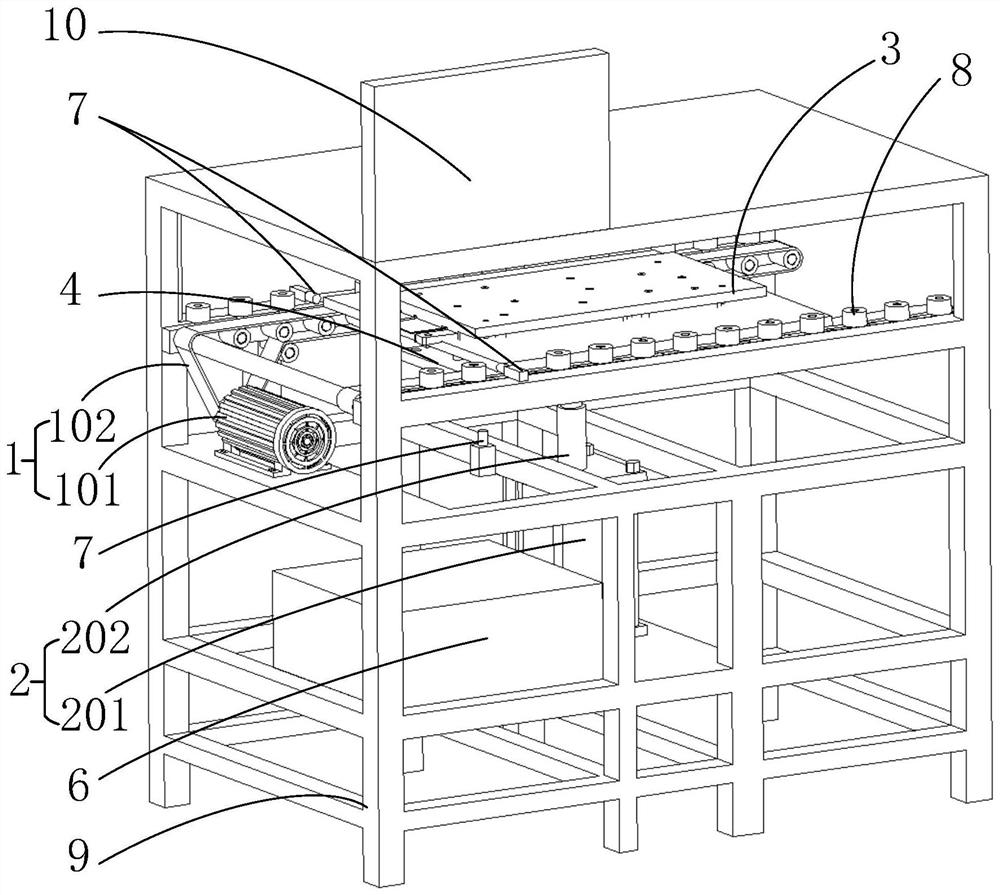
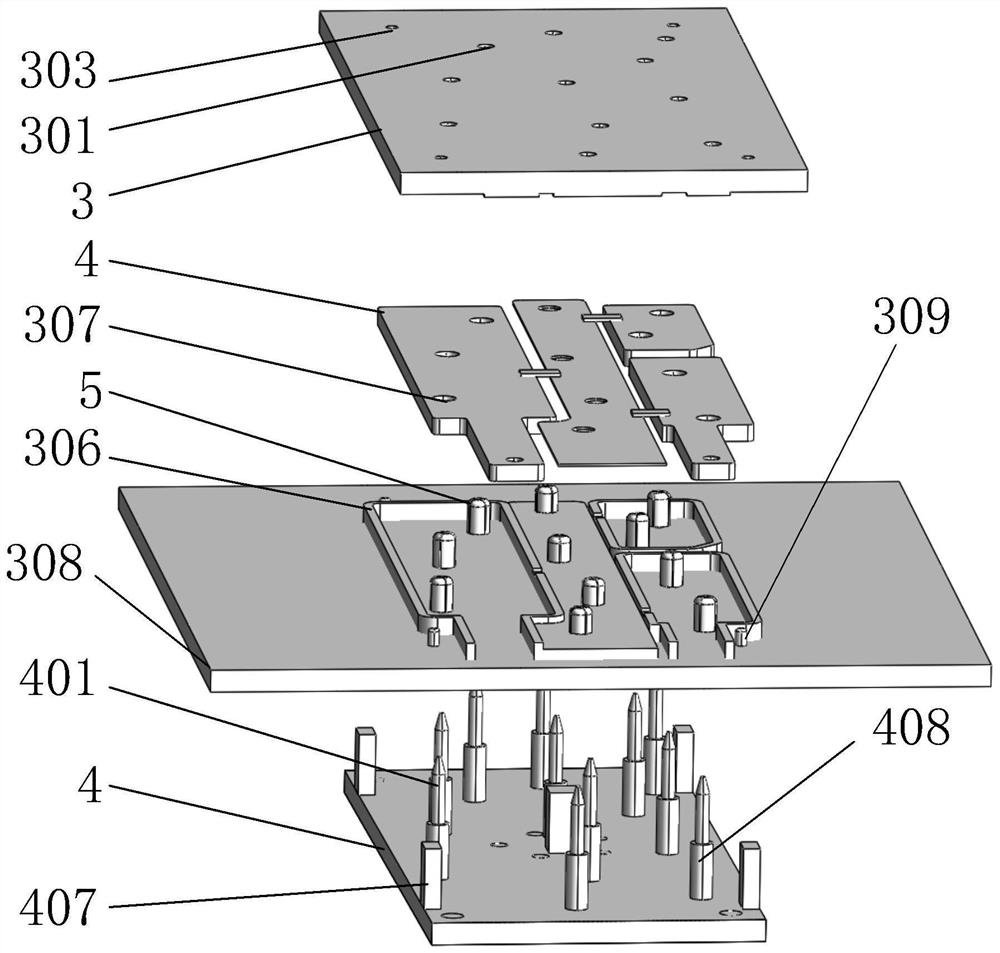
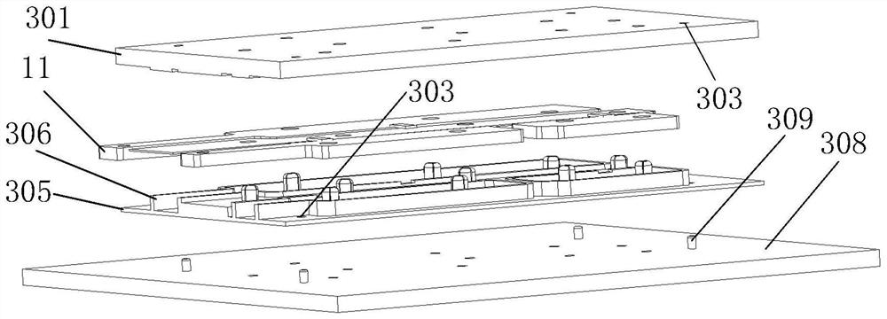
The invention belongs to the technical field of expansion riveting and pressing, and particularly relates to thermal expansion riveting pressing equipment. The automatic riveting device comprises a first driving assembly, a second driving assembly, a jig assembly and an expansion riveting device, the jig assembly is used for containing a workpiece and provided with a riveting piece, a guide hole is formed in the riveting piece in the axial direction, the expansion riveting device comprises a pin capable of being matched with the guide hole, and the pin protrudes relative to an expansion riveting device body. The first driving assembly is used for driving the jig assembly to move in the first direction, and when the jig assembly moves to a preset position in the first direction, the second driving assembly drives the expansion riveting device to move in the second direction, so that the pins are matched with the guide holes, the pins open the riveting piece in the radial direction, and the riveting piece and the workpiece are fixedly connected. According to the invention, the expansion riveting press-fit efficiency is improved.

Description


Claims


Application Information

Patent Timeline
Owner 广州安博新能源科技有限公司
Why Eureka
Try Eureka