Method and system for determining vehicle running environment

A technology of driving environment and judgment method, applied in anti-collision systems, vehicle components, vehicle safety arrangements, etc., can solve problems such as failure to detect targets ahead

Inactive Publication Date: 2006-11-22
HYUNDAI MOTOR CO LTD
View PDF0 Cites 2 Cited by
  • Summary
  • Abstract
  • Description
  • Claims
  • Application Information

AI Technical Summary

Problems solved by technology

At this time, according to the prior art, the vehicle 10 sometimes cannot detect the target 11 ahead.
If the vehicle 10

Method used


Image

  • Method and system for determining vehicle running environment
  • Method and system for determining vehicle running environment
  • Method and system for determining vehicle running environment

Examples


Embodiment Construction

[0021] Referring to the accompanying drawings, a preferred embodiment of the present invention will be described in detail below.

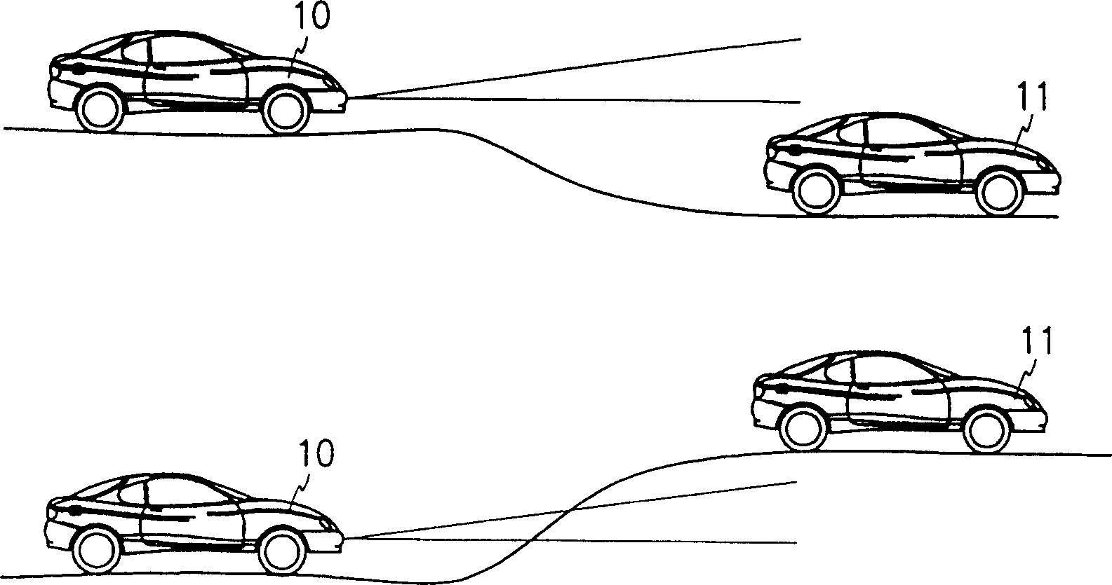
[0022] see figure 1 , according to a preferred embodiment of the present invention, the driving environment judging system of the vehicle 10 is a system for detecting a front target on the driving vehicle 10 .

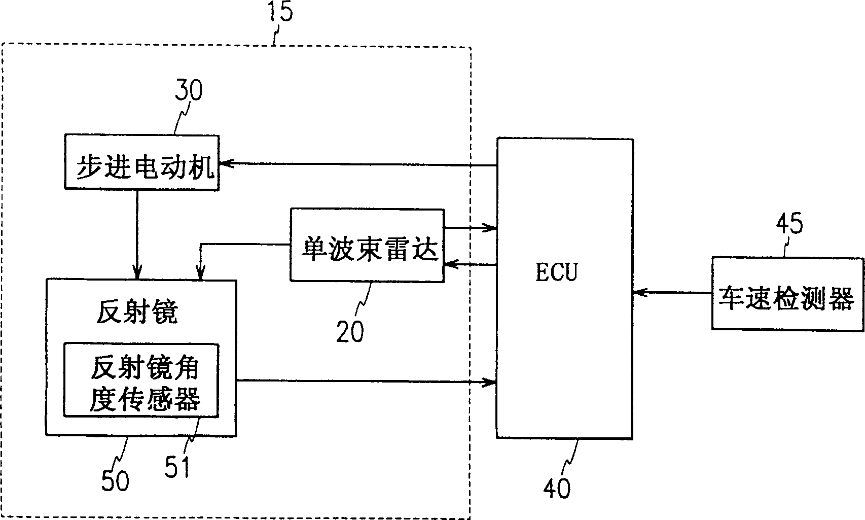
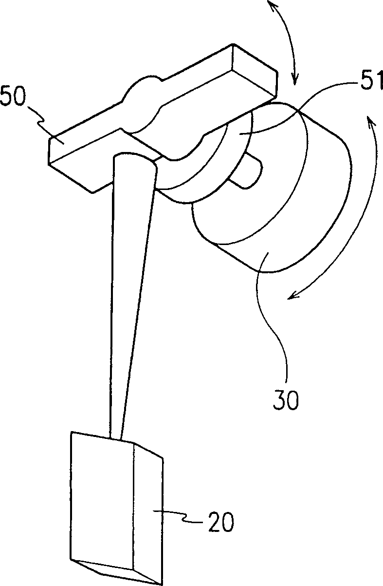
[0023] Such as figure 2 As shown, the preferred embodiment includes: a single-beam radar 20, which is used to transmit a radar beam for scanning, and detects the reflected wave reflected by the target in front; a reflector 50, which is used to adjust the elevation angle of the scanning radar beam ( Adjust according to its angular orientation); a mirror angle sensor 51, used to detect the angular orientation of the reflective mirror 50; a stepper motor 30, used to adjust the angular orientation of the reflective mirror 50; and an electrical control unit 40 ( The following is represented by ECU)

[0024] The elevation angle of a radar beam


PUM


Abstract

A method and system for judging a vehicle driving environment, comprising: scanning a radar beam emitted by a moving vehicle at a variable elevation angle; detecting reflected waves of the scanning radar beam reflected by a target in front; detecting the elevation angle of the scanning radar beam when detecting the reflected wave ; Calculate the relative speed of the target in front according to the reflected wave; detect the speed of the driving vehicle; calculate the absolute speed of the target in front according to the relative speed and the speed of the driving vehicle; compare the elevation angle with the predetermined angle; compare the absolute speed with the predetermined speed . The reflected wave reflected by the target in front is the reflected wave of an original transmitted radar beam scanned at a variable elevation angle. When the reflected wave is received, the elevation angle of the radar beam is detected, the relative speed of the target ahead is calculated according to the reflected wave, the absolute speed of the target ahead is calculated according to the speed and relative speed of the driving vehicle, and the vehicle driving environment is judged according to the elevation angle and absolute speed.

Description


Claims


Application Information

Patent Timeline
Owner HYUNDAI MOTOR CO LTD
Why Eureka
Try Eureka