Ultrasonic diagnostic device, signal processing device, and program
a diagnostic device and ultrasonic technology, applied in ultrasonic/sonic/infrasonic image/data processing, instruments, applications, etc., can solve the problems of deteriorating diagnostic performance, reducing measurement accuracy and reproducibility, etc., and achieve accurate measurement
- Summary
- Abstract
- Description
- Claims
- Application Information
AI Technical Summary
Benefits of technology
Problems solved by technology
Method used
Image

Examples
first embodiment
[0044]Hereinafter, embodiments of the invention will be described with reference to drawings.
[0045]
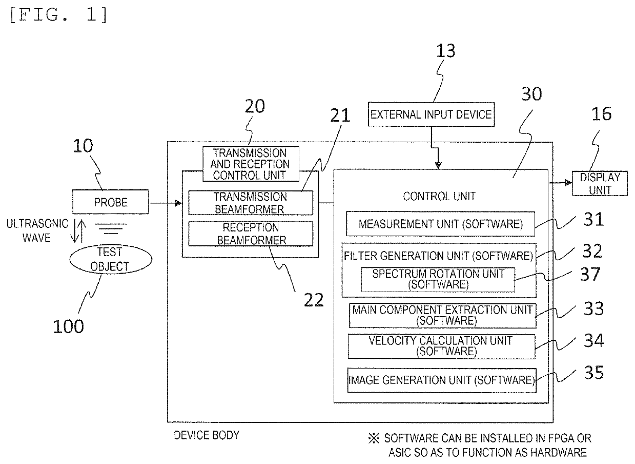
[0046]FIG. 1 shows a block diagram of a configuration example of an ultrasonic diagnostic device according to an embodiment. The ultrasonic diagnostic device of the present embodiment includes a transmission and reception control unit 20 and a control unit (signal processing device) 30. Further, a probe 10, an external input device 13, and a display unit 16 are connected to the ultrasonic diagnostic device.
[0047]The transmission and reception control unit 20 includes a transmission beamformer 21 that generates a transmission signal to be transferred to each vibrator constituting the probe 10, and a reception beamformer 22 that generates a reception signal for a predetermined point in an test object 100 based on output of each vibrator of the probe 10. Further, the control unit 30 includes a measurement unit 31, a filter generation unit 32, a main component extraction unit 33, a velocity c
second embodiment
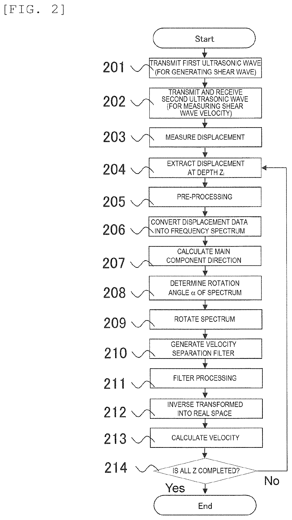
[0132]In the first embodiment described above, as shown in the flow of FIG. 2, a filter is generated for each depth Zi, and the rotation angle α is obtained. The method allows adaptive and accurate processing, but a calculation amount is large and processing takes time.
[0133]Therefore, in a second embodiment, using a fact that a range of the shear wave velocity is known to some extent according to a target organ, a filter and a rotation angle α are calculated in advance based on the range of the velocity and stored in the memory, and as shown in FIG. 21, in step 2103, the main component extraction unit 33 reads out and uses the filter and the rotation angle. At this time, the filters having the same shapes and the same rotation angles α are applied at all depths Zi. Accordingly, in the second embodiment, high-speed processing can be implemented. Steps 2101 to 2112 other than step 2103 in FIG. 21 are similar to the respective steps in FIG. 2, and a description thereof will be omitted.
[0
third embodiment
[0144]In the first embodiment and the second embodiment, a display example on the display unit 16 in FIG. 1 is shown in FIGS. 25 and 26.
[0145]In FIG. 25, a B mode image and elasticity map 2501 is displayed on the display unit of the device. The elasticity map is displayed in an ROI 2502 specified by the user. Further, a measured elastic modulus may be displayed as a numerical value on a part of the display unit.
[0146]In addition, in the display example in FIG. 25, a gradient distribution 2503 of a wavefront of the shear wave before processing and a gradient distribution 2504 of a wavefront of the main component of the shear wave after processing according to a processing method of the first embodiment or the second embodiment are displayed. The user can confirm the effect of the processing according to the first embodiment or second embodiment by comparing the gradient distribution of the wavefront before and after the processing.
[0147]FIG. 26 displays the B mode image and elasticity m
PUM
 Abstract
Description
Claims
Application Information
 - R&D Engineer
- R&D Manager
- IP Professional
- Industry Leading Data Capabilities
- Powerful AI technology
- Patent DNA Extraction
Browse by: Latest US Patents, China's latest patents, Technical Efficacy Thesaurus, Application Domain, Technology Topic.
© 2024 PatSnap. All rights reserved.Legal|Privacy policy|Modern Slavery Act Transparency Statement|Sitemap