Hollow ball plug and its manufacturing method

A manufacturing method and hollow technology, which is applied in the field of ball plugs and their casting, can solve the problems of hollow ball plugs such as heavy weight, unstable quality, and large thickness differences, and achieve the effects of material reduction, weight reduction, and excellent quality

Inactive Publication Date: 2007-02-28
律泉精密股份有限公司
View PDF2 Cites 0 Cited by
  • Summary
  • Abstract
  • Description
  • Claims
  • Application Information

AI Technical Summary

Benefits of technology

This technology makes it possible for balls made from plastic that are lighter than traditional metal ones while still being cost-effective or better at performing their intended function properly.

Problems solved by technology

This patented technical problem addressed in the patents relates to improving the efficiency at producing balls for use in valves due to their size and mass. Specifically, current methods involve adding extra materials or processes after production, but these techniques have limitations such as requiring multiple steps and being difficult to handle on larger sizes.

Method used


Image

  • Hollow ball plug and its manufacturing method
  • Hollow ball plug and its manufacturing method
  • Hollow ball plug and its manufacturing method

Examples


Embodiment Construction

[0029] In order to have a more detailed and definite understanding of the technology and means on the object and method of the present invention, a preferred specific embodiment of the present invention is cited and described as follows in conjunction with the drawings:

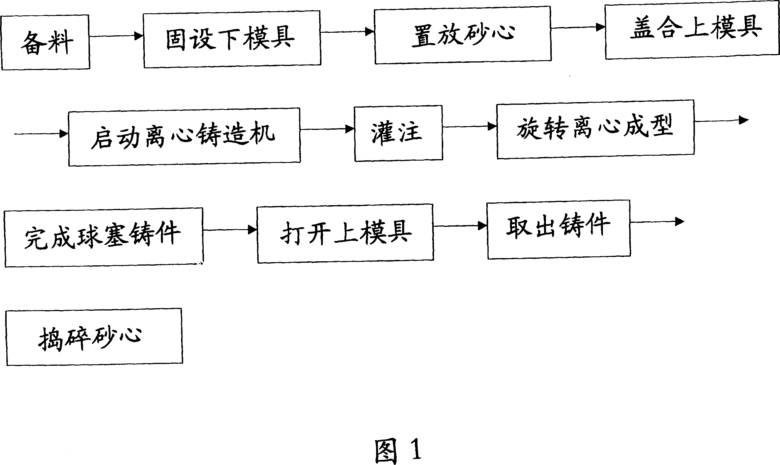
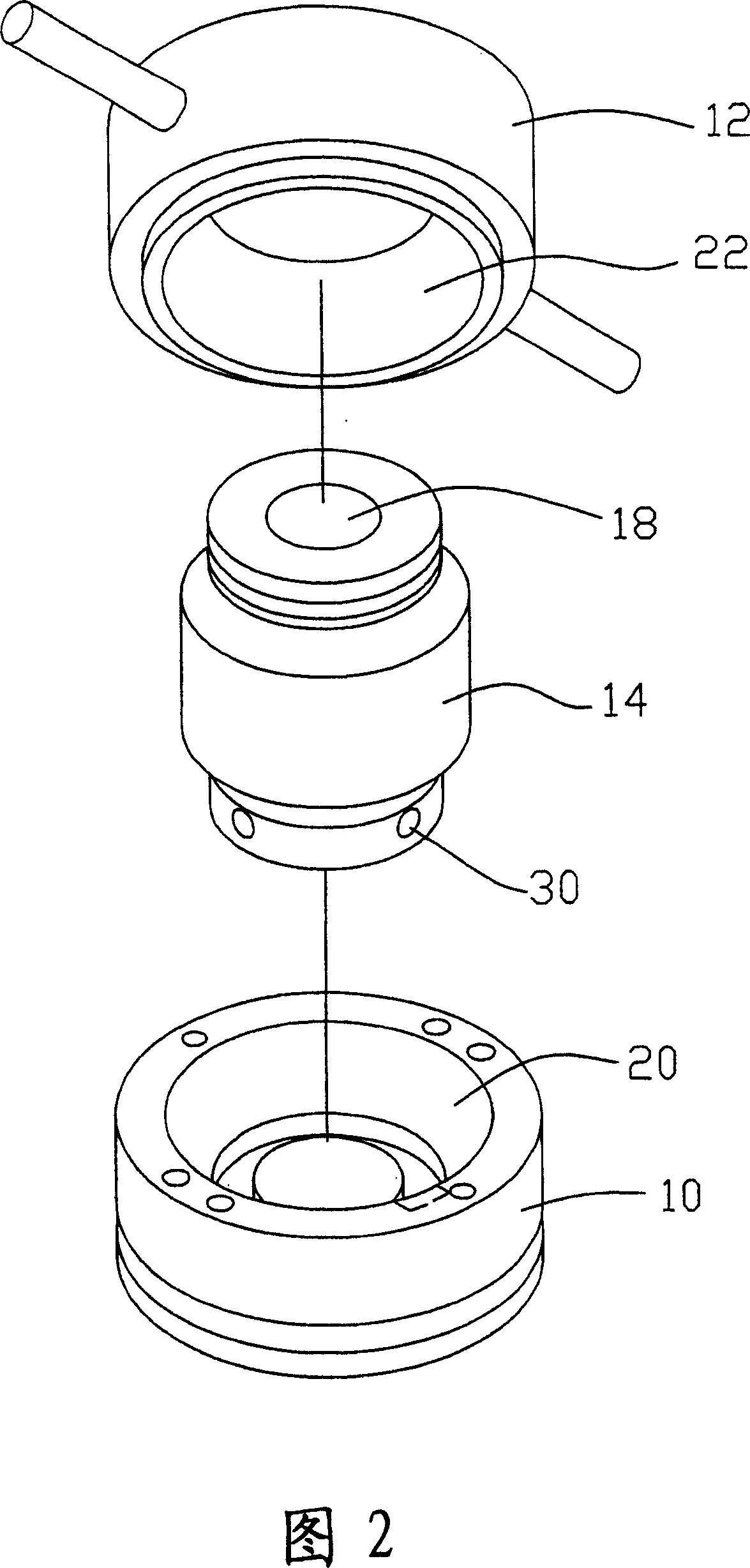
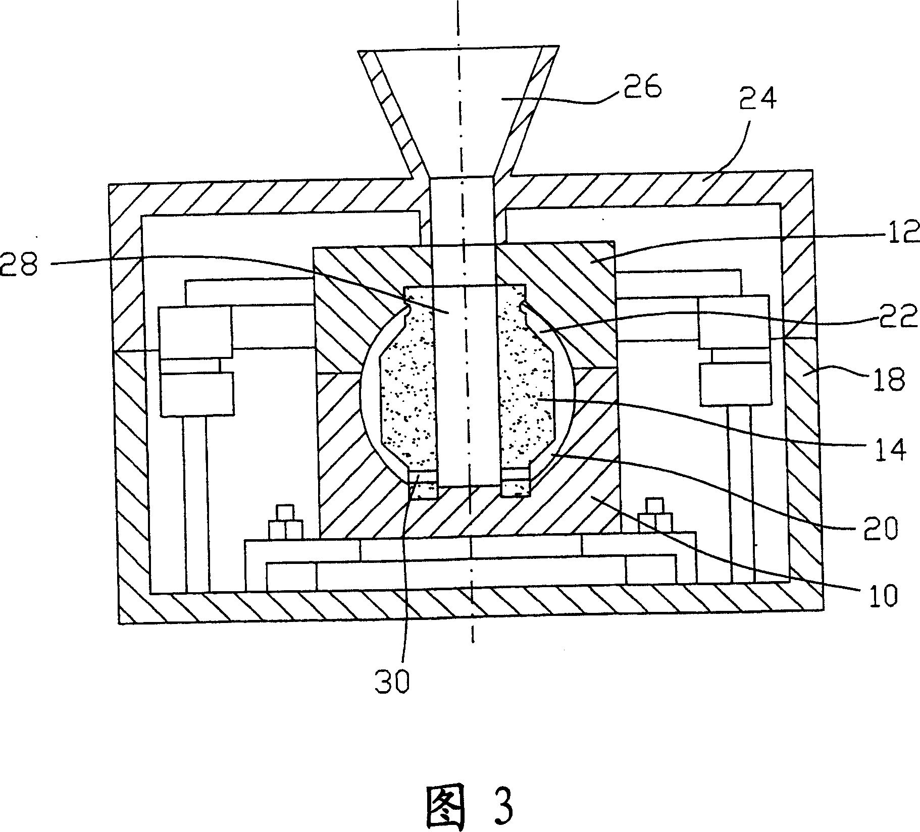
[0030] Please refer to shown in Fig. 1, it is a kind of asymmetric type vertical centrifugal casting method flow chart of the present invention, and cooperate to refer to shown in Fig. 2, Fig. 3, Fig. 4 and Fig. 5, Fig. 6, its whole manufacturing process includes the following Steps:

[0031] Material preparation: heating the metal material until it melts into a liquid state;

[0032] Fix the lower mold: the lower mold cavity 20 is preset as the lower mold 10 in the shape of the lower half of the ball plug, and the lower mold 10 is locked and fixed in the centrifugal casting machine 18;

[0033] Place the sand core: the sand core 14 whose shape is the hollow shape of the ball plug and has a central channel is p


PUM


Abstract

The invention provides a hollow bulb stopper and its manufacturing method. The hollow bulb stopper is hollow globose plug. We pour the melted metal liquid into the on-the-fly clip mould made up of two parts, upper and lower. There is die cavity with the shape of the bulb stopper and sand core whose shape is same with the hollow shape of the bulb stopper. The sand core has a central channels and the metal liquid is poured into through the central channel and penetrates the interval channel at the bottom of the sand core to make the metal liquid distribute equably in the clearance between the die cavity and the sand core. Till it is cool, we stop circumgyrating the mould, demolds it, mash the sand core and get the bulb stopper. The invention can effectively simplify the technique of the thin wall bulb stopper and provides bulb stoppers with higher quality.

Description


Claims


Application Information

Patent Timeline
Owner 律泉精密股份有限公司
Why Eureka
Try Eureka