Degasification inducation structure of aerosol container, method of indicating degasification and degasification device
The technology of an aerosol container and a tool is applied in the fields of degassed indication structure, degassed indication and degassing tool of aerosol container, which can solve the problems such as inability to judge and inability to distinguish the outgassing of a discarded container at a glance , to achieve the effect of avoiding explosion and fire
- Summary
- Abstract
- Description
- Claims
- Application Information
AI Technical Summary
Benefits of technology
Problems solved by technology
Method used
Image

Examples
Embodiment 1
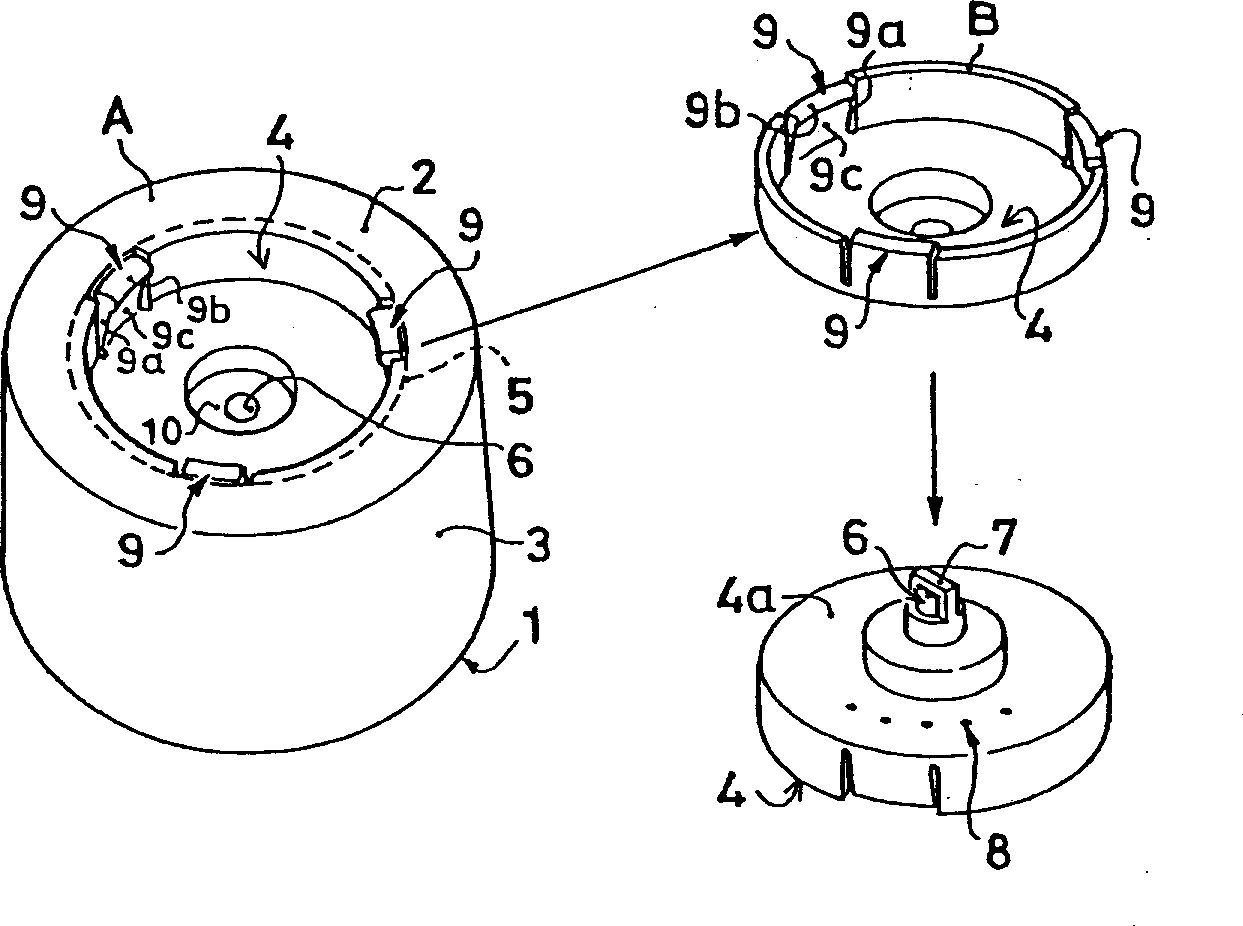
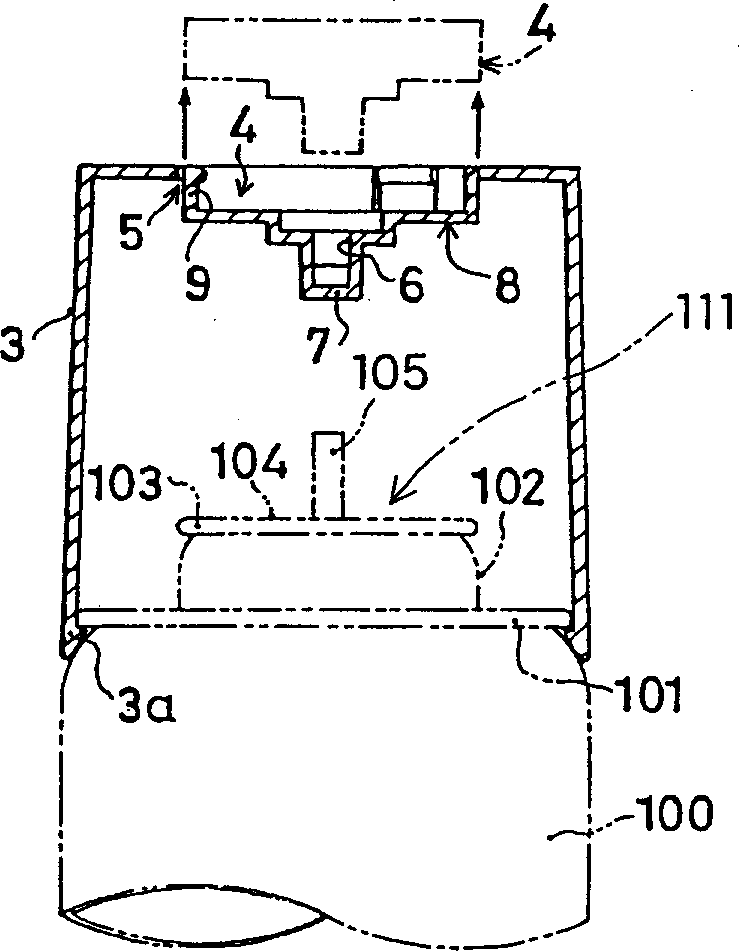
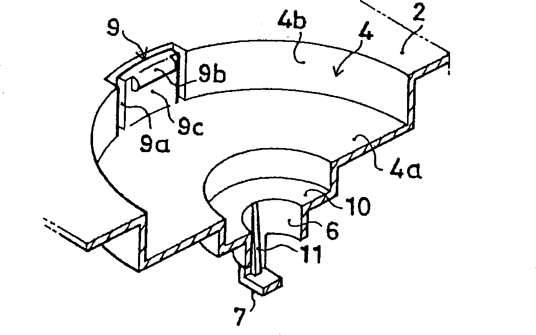
[0057] Figure 1~6 The shown degassing tool 1 is used as figure 2 The lid of the shown aerosol container 100 is used, as shown in Figure 5 (a), by using it up and down with respect to the aerosol container 100, it can be used as a degassing tool, and can also be used as an attached Aerosol cap for degassing indicator device.
[0058] Here, the aerosol container 100 is a steel container, which has a curling portion 101 formed on the upper edge of the wall tube of the container, and an upper bulging portion 102 is formed on the upper central portion of the container, and the upper portion of the bulging portion 102 is The peripheral edge serves as the curled portion 103 . The installation cup 104 of the aerosol valve 111 is installed on the above-mentioned expansion part 102 by crimping, and the rod-shaped rod 105 is protrudingly arranged on the central part. When the rod 105 is pressed inward, the aerosol gas inside will squirt.
[0059] The degassing tool 1 is integrally for
Embodiment 2
[0083] Figure 12 and the degassing tool 31 shown in Figure 13 are not like the aforementioned degassing tool 1, a part of the degassing tool (separation body B) with a degassing indicating device is separated during or after degassing, Instead, the entire degassing tool is installed on the aerosol container, and the rod is pressed by maintaining the cap installed state, and the degassing indicating device is attached at the same time, and the degassing tool is thus constituted.
[0084] That is, the degassing tool 31 is integrally formed by plastic injection molding into a bottomed flat cylindrical shape having approximately the same diameter as the outside of the mounting cup 104 defined by the top surface 32 and the peripheral side 33. In the top surface 32, a gas ejection hole 36 located in the central part is provided, and a degassed indicating device 38a surrounding the gas ejection hole 36 of the cover is attached. At the same time, a degassed indicating device 38b is attac
Embodiment 3
[0092] Such as Figure 14 As shown, the degassing tool 41 is a degassing tool without a degassed indicating device, but has such a structure: the structure has a degassed indicating body 51 with a degassed indicating device 55 .
[0093] The degassing tool 41 is formed with a bottomed circular shape consisting of a top surface 42a and a peripheral side surface 42b, and a recessed portion 43 that is concave to the bottomed cylindrical inner side is formed in the top surface 42a. In the recess 44, an annular groove 45 is formed on the outside of the fitting recess 44 in the recess 43, and a gas ejection hole 46 is formed at the center of the bottom surface 44a of the fitting recess 44. The inner part of the cylinder is provided with a direction changing part 47 that shields the axial direction.
[0094] Here, the above-mentioned fitting recess 44, gas ejection hole 46, and direction changing portion 47 are formed in the same manner as the fitting recess 24, gas ejection hole 26, a
PUM
 Abstract
Description
Claims
Application Information
 - R&D Engineer
- R&D Manager
- IP Professional
- Industry Leading Data Capabilities
- Powerful AI technology
- Patent DNA Extraction
Browse by: Latest US Patents, China's latest patents, Technical Efficacy Thesaurus, Application Domain, Technology Topic.
© 2024 PatSnap. All rights reserved.Legal|Privacy policy|Modern Slavery Act Transparency Statement|Sitemap