Thermosensitive head

A technology of thermal head and heating element, applied in the field of thermal head, which can solve the problems of reduced printing quality and easy retention, etc.

Inactive Publication Date: 2003-06-18
ALPS ALPINE CO LTD
View PDF0 Cites 5 Cited by
  • Summary
  • Abstract
  • Description
  • Claims
  • Application Information

AI Technical Summary

Problems solved by technology

[0013] However, in the conventional thermal head, recesses 12c, 12d are formed on the left and right slopes of the raised portion 12b of a given height on the surface of the insulating layer 12.
[0014] Therefore, when the lowered thermal head 11 moves in the arrow A direction while printing the ink of the printing ribbon 18 on the printing paper 19 at the position of the platen cylinder (not shown in the figure), On the left side of the drawing of the heating element 13a, becau

Method used


Image

  • Thermosensitive head
  • Thermosensitive head
  • Thermosensitive head

Examples


Embodiment Construction

[0025] specific implementation plan

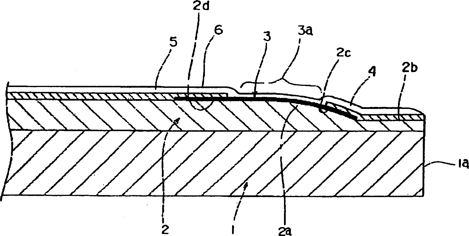
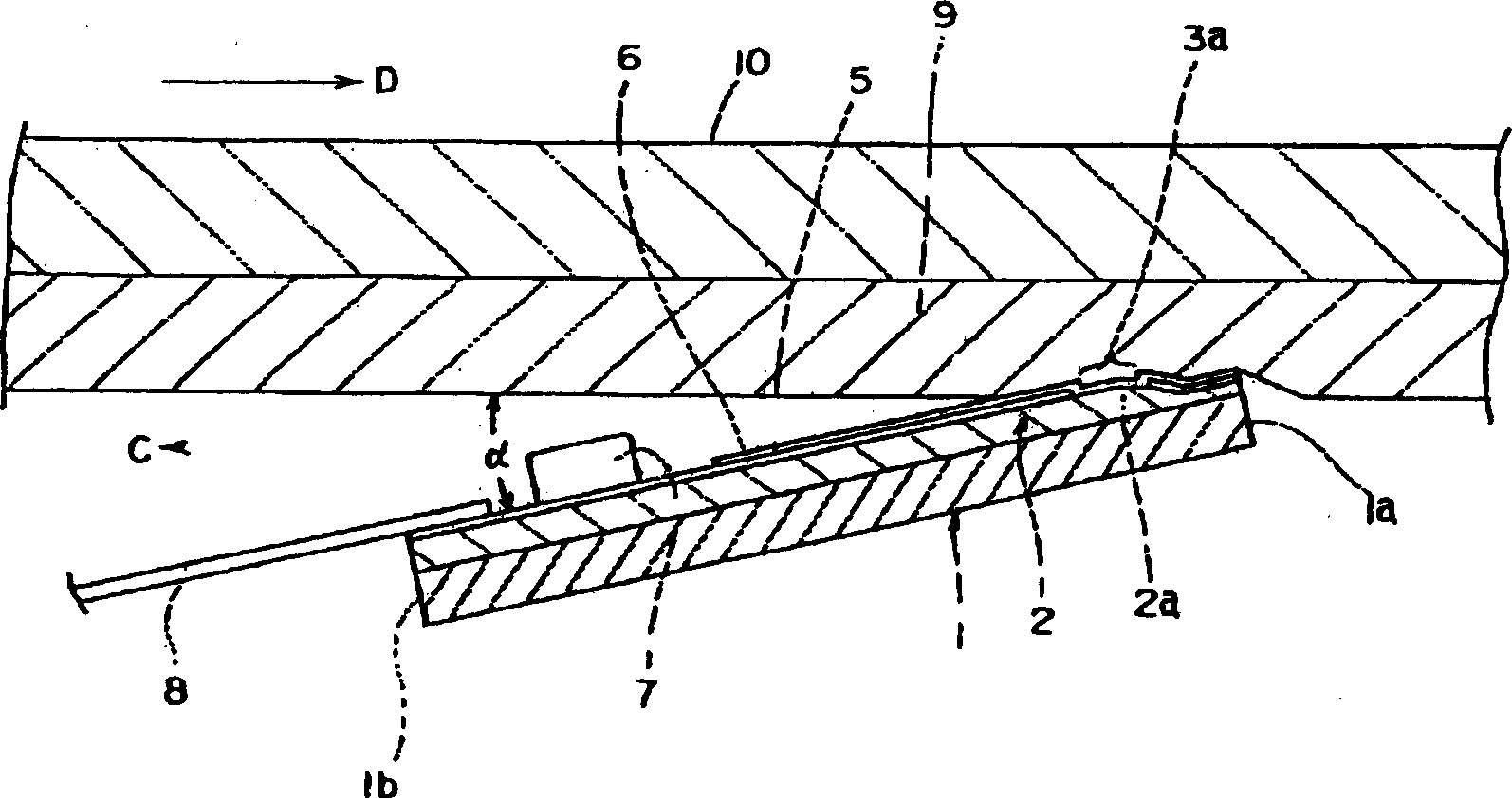
[0026] The thermal head of the present invention will be described in detail below with reference to the accompanying drawings. figure 1 It is a sectional view of main parts of the thermal head related to the present invention, figure 2 It is a schematic diagram illustrating the printing operation of the thermal head of the present invention.

[0027] First, the thermal head of the present invention, such as figure 1 As shown, a substrate 1 with good heat dissipation is arranged, and a thermal insulation layer 2 made of a glaze with good thermal insulation is formed on the substrate 1 .

[0028] The thermal insulation layer 2 is partially protruded on the surface by photolithography 2 technology to form a convex portion 2a. The convex portion 2a has a cross-sectional shape in a direction perpendicular to the direction in which the heat generating elements 3a are arranged to be described later, and is formed as an inclined surface 2c tow


PUM

PropertyMeasurementUnit
Heightaaaaaaaaaa

Abstract

The invention provides a thermal head which can execute high-quality printing by preventing foreign matters such as dust from accumulating at the printing time at a part where a thermal insulating layer is formed. The thermal insulating layer 2 of the thermal head has a surface partially projected thereby forming a projecting part 2a with a vertex part. Heating elements 3a are set at the surface of the projecting part 2a. A cross sectional shape of the projecting part 2b in a direction orthogonal to the arrangement direction of heating elements 3a has an inclined face 2c formed at a face side 2b. The one face side 2b is formed lower than the other face side 2d. The projecting part 2a is formed to have a height from the one face side 2b of 5-50 [mu]m.

Description


Claims


Application Information

Patent Timeline
Owner ALPS ALPINE CO LTD
Why Eureka
Try Eureka