Stirring fan mounting structure for microwave oven

A technology for installation structure and microwave oven, which is applied in household stove/stove, household heating, lighting and heating equipment, etc. It can solve the problems of complicated installation process and increased manufacturing cost, and achieve good stability, easy operation and cost saving. Effect

Inactive Publication Date: 2003-11-12
LG ELECTRONICS (TIANJIN) APPLIANCES CO LTD
View PDF0 Cites 1 Cited by
  • Summary
  • Abstract
  • Description
  • Claims
  • Application Information

AI Technical Summary

Benefits of technology

This innovation allows for easy installation by eliminating any extra hardware needed on existing equipment used with an electric or gas cooking appliance. It also improves its overall performance while being more stable over time compared to traditional methods like brazing iron bars.

Problems solved by technology

This patented technical problem addressed in the current design for microwaving ovens involves improving upon conventional methods used for installing fans onto their chambers or attaching them externally around the chamber walls. These techniques involve adding extra parts such as brackets, bolts, and covers, making it difficult to maintain alignment accuracy while fixing the fan.

Method used


Image

  • Stirring fan mounting structure for microwave oven
  • Stirring fan mounting structure for microwave oven
  • Stirring fan mounting structure for microwave oven

Examples


Embodiment Construction

[0024] The installation structure of the microwave oven stirring fan of the present invention will be further described in detail in conjunction with the accompanying drawings and specific embodiments:

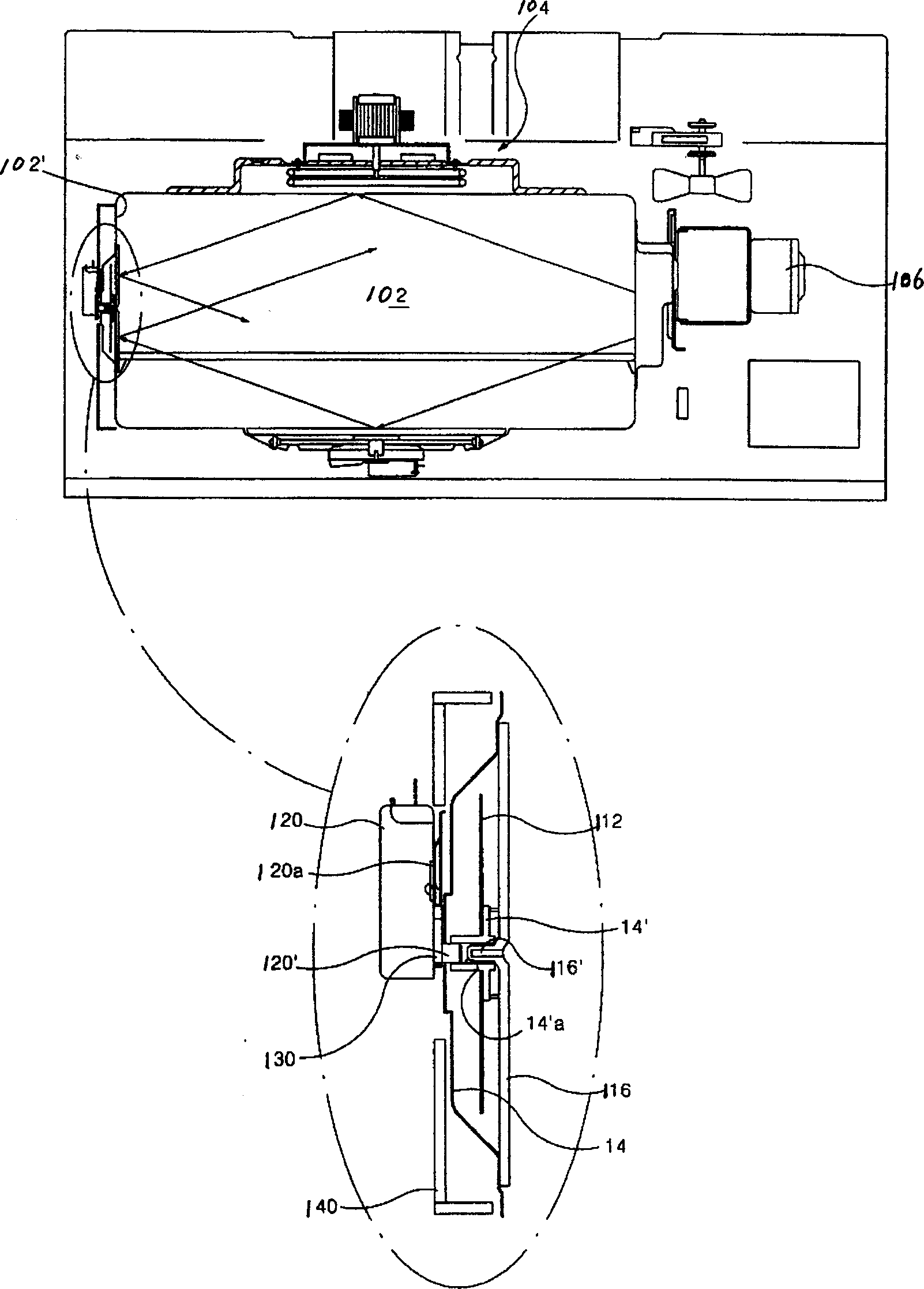
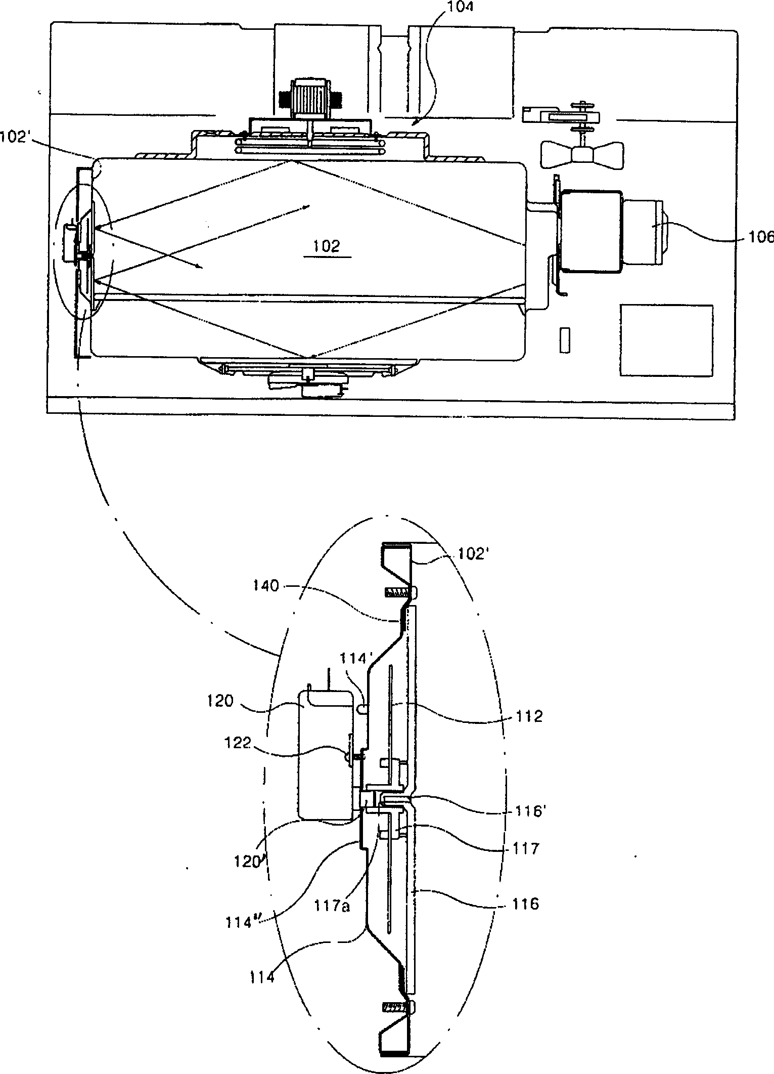
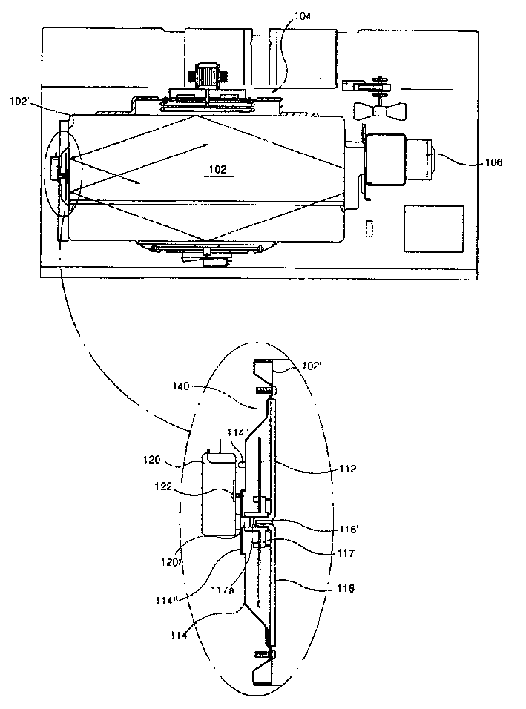
[0025] Such as figure 2 As shown, a convection heater assembly 104 is arranged on the top surface of the cooking chamber 102 of the microwave oven, a magnetron 106 is arranged on a side wall of the cooking chamber 102, and a magnetron 106 is arranged on the side wall 102' opposite to the magnetron 106 in the cooking chamber 102. A stirring fan 112 is provided. The function of the stirring fan 112 is to reflect the microwave generated by the magnetron 106 . The stirring fan 112 is driven by a fan motor 120 .

[0026] The installation structure of the stirring fan of the present invention comprises: stirring fan 112, heat insulating shell 140, side wall 102', support 117 and fan cover 116; The middle part of described side wall 102' has a circular hole, and heat insulating shell 1


PUM


Abstract

The structure of the mixing fan comprises the mixing fan, the heat-insulation enclosure, the sidewall, the bracket and the cover of the fan. The heat-insulation enclosure closes down the circular hole on the middle part of the sidewall so as to form raised fitting room outwardly. The supporting pillar is formed in the up part and the boss is formed in the middle part outside the fitting room. There are the through hole and the screw hole in the middle part of the boss. The mixing fan in the fitting room is installed in the bracket with the through hole in its middle part. The convex post formed on the middle part of the fan cover is inserted into the central through hole in the bracket and the edge of the fan cover is inserted into the fan cover slot in the sidewall of the cooking room. The mixing fan can be hard installed without need of additional bracket providing the features of good stability, easy of use and economy cost

Description


Claims


Application Information

Patent Timeline
Owner LG ELECTRONICS (TIANJIN) APPLIANCES CO LTD
Why Eureka
Try Eureka