Air conditioner and control method thereof

A control method and air conditioner technology, which is applied to air conditioning systems, heating and ventilation control systems, heating methods, etc., and can solve the problems of not considering the indoor space of indoor units, difficulty in uniform temperature, and restrictions on air volume adjustment.

Inactive Publication Date: 2004-01-07
SAMSUNG ELECTRONICS CO LTD
View PDF0 Cites 0 Cited by
  • Summary
  • Abstract
  • Description
  • Claims
  • Application Information

AI Technical Summary

Benefits of technology

The technical effect that this technology allows for smoother movement within an environment by changing its orientation based on how it's supposedly being moved around or when people are present at different locations inside the room. This creates more realistic feeling compared to traditional methods like fans blowing outdoor cold outside through windows or opening doors.

Problems solved by technology

Technological Problem: Current Air Conditioners (AC) have difficulty efficiently cooled rooms due to their design restricting them towards just two ways for exhaustion or directional distribution of hot/cold gases. Additionally, they often require multiple fans and motors to achieve these goals.

Method used


Image

  • Air conditioner and control method thereof
  • Air conditioner and control method thereof
  • Air conditioner and control method thereof

Examples


Embodiment Construction

[0019] Embodiment of the invention

[0020] Hereinafter, preferred embodiments of the present invention will be described in detail with reference to the drawings.

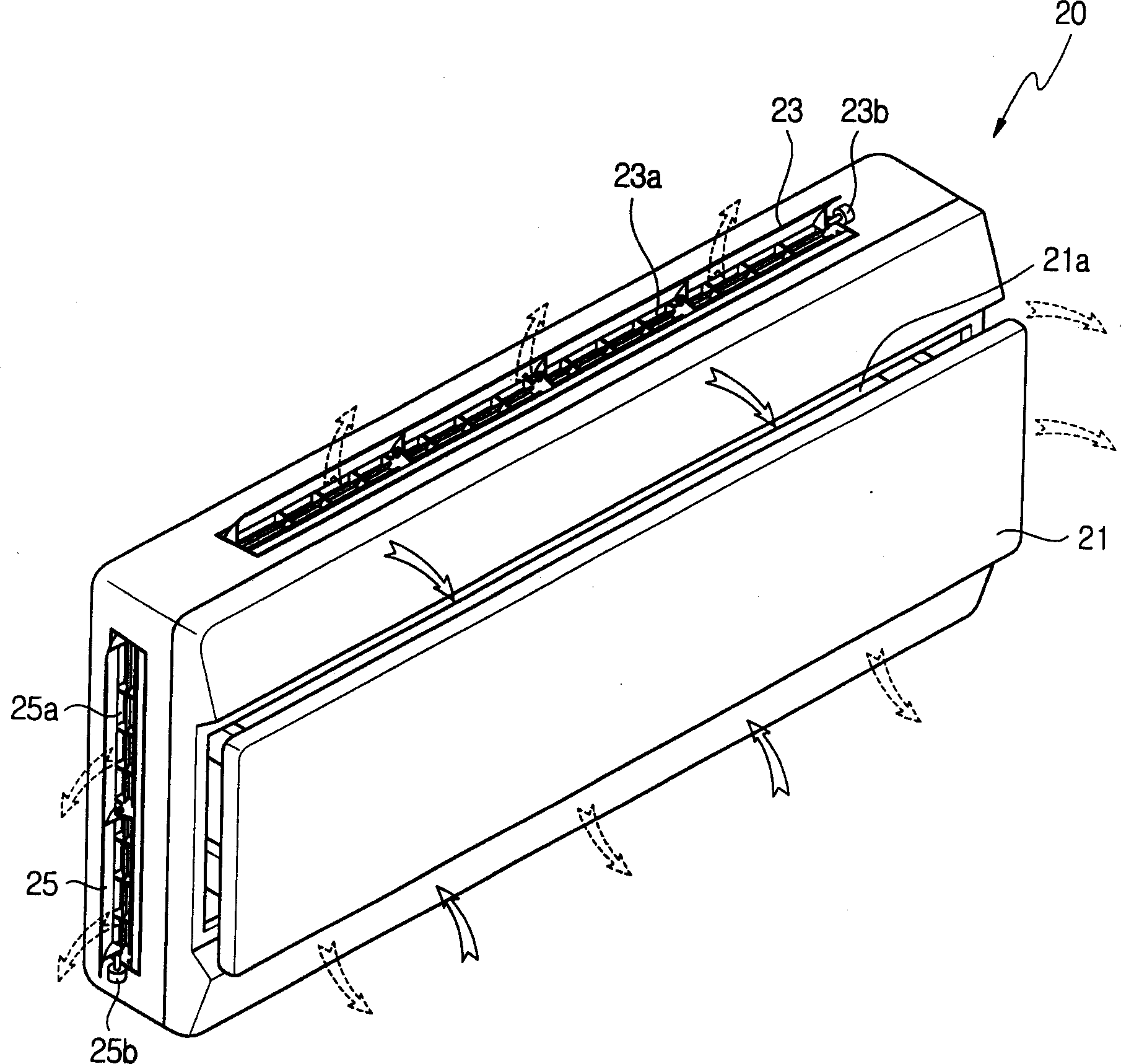
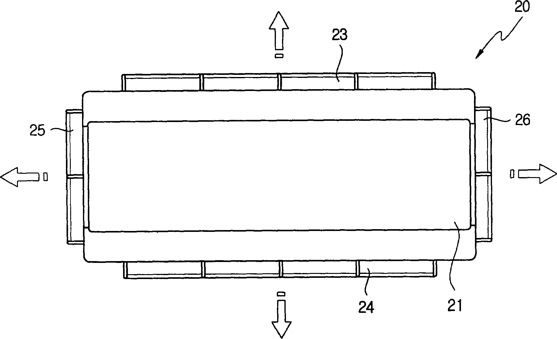
[0021] figure 2 is a schematic perspective view of the air conditioner of the present invention, image 3 It is the front view of the air conditioner of the present invention.

[0022] As shown in these figures, the air conditioner of the present invention is provided with an indoor unit main body 20 mounted on a wall and connected to an outdoor unit via a refrigerant line. The main body 20 includes a suction grill 21 and discharge grills 23 , 24 , 25 , 26 . The above-mentioned suction grill 21 is provided on the front surface of the main body, and advances and retreats in the front-rear direction for opening and closing the suction port 21a. The above-mentioned discharge grilles 23, 24, 25, 26 are used to open and close the discharge ports 23a, 24a, 25a, 26a, and are provided rotatably on the upper, lower, left


PUM


Abstract

An air conditioner and a control method of the same are provided to change flowing of discharged air by controlling opening and closing operation of a plurality of outlets. An air conditioner includes discharge louvers opening and closing a plurality of outlets discharging air having exchanged heat in an indoor heat exchanger into an indoor space; louver motors(23b,24b,25b,26b) driving the discharge louvers; and a control part(30) controlling opening and closing operation for the outlets to change flowing of air discharged into the indoor space. A method includes a normal operating mode in which all of the outlets are opened to discharge air having exchanged heat; and a wide mode in which the outlets are successively opened or closed to change flowing of air having exchanged heat. Wind direction is successively changed thereby to generate wind like natural wind to allow a user to feel cozy. Air having exchanged heat is focused thereby to reach wide range so as to rapidly and evenly cool the indoor space.

Description


Claims


Application Information

Patent Timeline
Owner SAMSUNG ELECTRONICS CO LTD
Why Eureka
Try Eureka