Small vacuum filling device

A vacuum filling and small-scale technology, which is applied in the direction of equipment for loading into pressure vessels, container filling methods, gas/liquid distribution and storage, etc. It can solve the problems of inconvenient installation of valve devices, small equipment capacity, small pipelines, etc., to achieve Increased uptime, reduced manufacturing costs, and cost reduction effects

Inactive Publication Date: 2005-08-03
SOUTH CHINA UNIV OF TECH
View PDF0 Cites 0 Cited by
  • Summary
  • Abstract
  • Description
  • Claims
  • Application Information

AI Technical Summary

Benefits of technology

This patented technology solves problems by providing better ways to securely connect both parts together during assembly without requiring any extra steps like bolting them separately. By doing this, it simplifies production processes while also reducing costs associated therewith. Additionally, the design allows for more efficient operation over longer periods due to its ability to actively control pressure applied across multiple components. Overall, these improvements improve the overall effectiveness and longevity of the apparatus used for maintaining proper air conditioned conditions within industrial facilities such as chemical plants, power generators, automobiles, etc., resulting in improved efficiency and reduced maintenance expenses.

Problems solved by technology

The technical problem addressed by this patented method for efficiently producing high purity gases during manufacturing processes that require precise control over pressure levels can include ensuring proper sealing between different parts within an apparatus while avoiding any unwanted substances from entering through leaks caused by improper installation of certain components like valves.

Method used


Image

  • Small vacuum filling device

Examples


Embodiment Construction

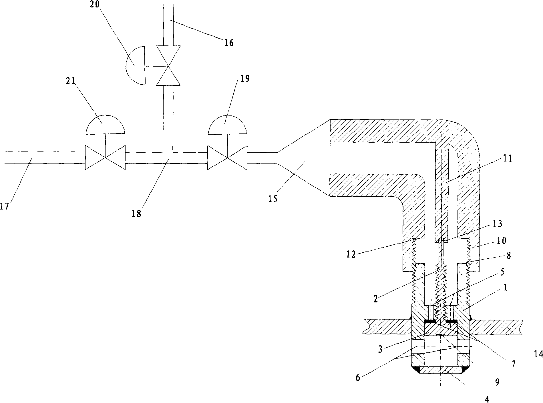
[0019] In order to better understand the present invention, the present invention will be further described below in conjunction with the accompanying drawings.

[0020] Such as figure 1 As shown, the small vacuum filling device of the present invention is composed of three parts, including a filling valve, a sealing pipe wrench, and a T-shaped valve pipe. The filling valve is mainly composed of a valve base 1, a valve stem 2, a cylindrical sealing body 3, and a The sliding cover 4 is composed of the valve base 1 in an H-shape, with threads in the middle of its transverse wall, the valve base 1 is connected with the valve stem 2 through the threads of the transverse wall, and the lower end of the valve stem 2 is integrated with the upper end of the cylindrical sealing body 3; The outer peripheral surface of the cylindrical sealing body 3 is in contact with the inner side of the side wall of the valve base body 1, and the first group of canned gas inlet holes 5 are opened on the t


PUM


Abstract

The small vacuum filling device consists of three parts including filling valve, sealed pipe spanner and T valve pipe. The filling valve consists of mainly valve base body with thread and two groups of filled gas inlet holes, valve rod screwed to the valve base body, cylindrical sealing body connected to the valve rod, and anti-falling cap welded to the lower end of the valve base body. The sealed pipe spanner has inner thread in the lower wall for connection with the valve base body and front end welded to one connection pipe of the T valve pipe. The present invention may be welded directly onto small container for convenient filling.

Description


Claims


Application Information

Patent Timeline
Owner SOUTH CHINA UNIV OF TECH
Why Eureka
Try Eureka