Camera system

A camera and server technology, applied in the field of camera systems, can solve the problems of attaching importance to the security of the surveillance system and insufficient

Inactive Publication Date: 2006-03-01
KOKUSA ELECTRIC CO LTD
View PDF3 Cites 1 Cited by
  • Summary
  • Abstract
  • Description
  • Claims
  • Application Information

AI Technical Summary

Benefits of technology

The technical effect of this patented technology allows cameras with different settings (such as resolution) on one hand while still being able to capture images without compromising their privacy. This makes managing accessing sensitive data more convenient than traditional systems where each user has its own setting options. Additionally, there may exist applications such as connecting wireless sensors into an internet connection instead of directly attaching them to the network itself.

Problems solved by technology

This technical problem addressed in this patents relating to systems called Video Surveying System(VSSS) involves managing different types of data streams among multiple clients' equipment while maintaining secure connections during wireless networks. Existing methods require manual intervention and slow down responses due to increased workload requirements. Additionally, these techniques have limitations in providing flexibility across different modes based upon factors like resolution setting levels, gaming capabilities, and recording preferences.

Method used


Image

  • Camera system
  • Camera system
  • Camera system

Examples


Embodiment Construction

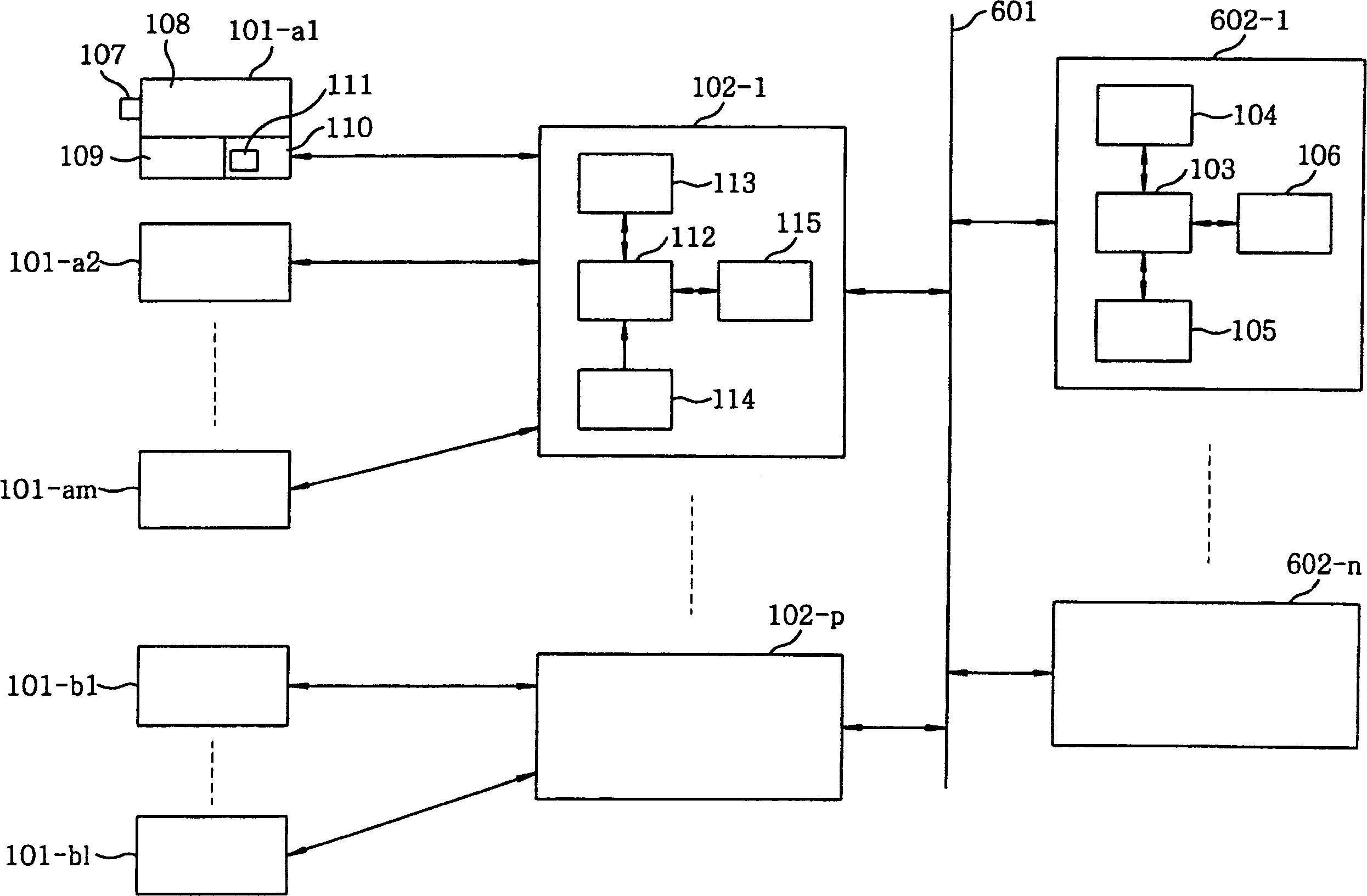
[0047] figure 1 It is a block diagram showing a schematic configuration of an embodiment of the present invention. figure 1 In, 601 with Image 6 As shown, the communication network generally consists of signal transmission paths. 602-1, . . . , 602-n are terminal devices connected to the communication network 601, such as client terminal devices. In addition, when terminal devices are collectively referred to as terminal devices 602, 101-a1, 101-a2, ... 101-am, 101-b1, ... 101-b1 are camera devices, for example, camera device 101- a1, 101-a2, . . . 101-am constitute, for example, a camera device group A ranging from several to tens of cameras. Similarly, the camera devices 101-b1, . . . 101-b1 constitute the camera device group B. FIG. In addition, when collectively referring to camera devices, they are referred to as camera devices 101. 102-1, ... 102-p are camera servers, figure 1 Among them, one camera server 102-1 is configured to collectively manage a plurality of ca


PUM


Abstract

To solve the problem that the operability of presetting of a camera device has been inadequate for many and unspecified users to do desired presetting registration or changes when a plurality of camera devices and numerous terminal devices are connected by a communication transmission line such as the Internet, as a pan or tilt position, and a zoom or focus position are stored in the camera device itself. A camera system comprises at least a camera device, a camera server coupled onto the camera device, a plurality of terminal devices, and a transmission line connecting the terminal devices to the camera server. The terminal devices have a function of inputting a user ID for using the terminal device. The camera server has a central processor and a first storage. The central processor connects a terminal device to the camera device based on a connection request from the terminal device, and selects the predetermined presetting condition of the selected camera device. The central processor also relates the user ID, the connected camera device, and the selected presetting condition, and stores them in the first storage of the camera server as a first table.

Description


Claims


Application Information

Patent Timeline
Owner KOKUSA ELECTRIC CO LTD
Why Eureka
Try Eureka