Connection structure between vacuum cleaner motor stator enamelled wire connection end and connection terminal

A technology of connection terminal and motor stator, which is applied in the field of connection structure between enameled wire connection port and connection terminal of vacuum cleaner motor stator, can solve the problems of increasing process and working hours, irregular appearance, affecting flow operation, etc., to achieve neat appearance, The effect of saving man-hours

Inactive Publication Date: 2006-06-07
LG ELECTRONICS (TIANJIN) APPLIANCES CO LTD
View PDF0 Cites 1 Cited by
  • Summary
  • Abstract
  • Description
  • Claims
  • Application Information

AI Technical Summary

Benefits of technology

The technical effect of this new design makes it easier and more efficient to connect multiple electrical devices together with an insulated electric cord without having any extra steps or tools needed during installation process.

Problems solved by technology

This patented technical problem addressed in this patents relates to improving connections for electrical devices such as motors used in industrial applications due to poor contact caused by manual handling during manufacturing processes or damage from external sources like impacts. Additionally, there may occur issues where the exposed metal crumbles over time causing short circuits which affect performance.

Method used


Image

  • Connection structure between vacuum cleaner motor stator enamelled wire connection end and connection terminal
  • Connection structure between vacuum cleaner motor stator enamelled wire connection end and connection terminal

Examples


Embodiment Construction

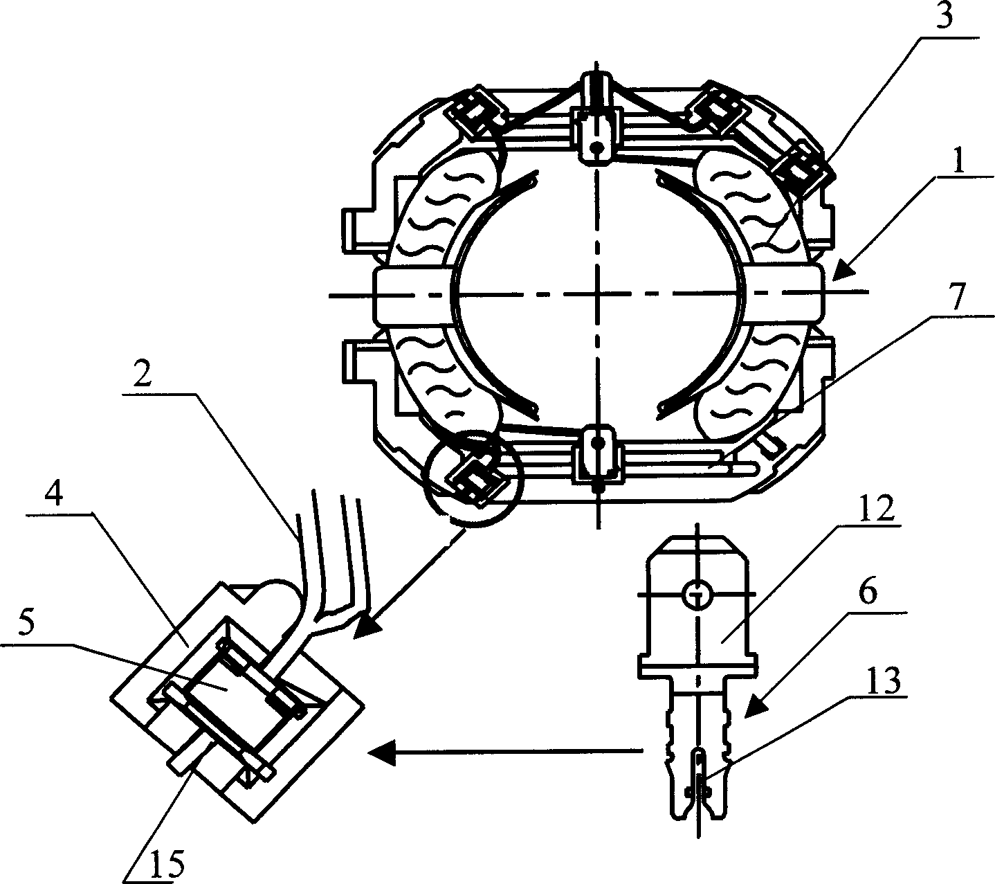
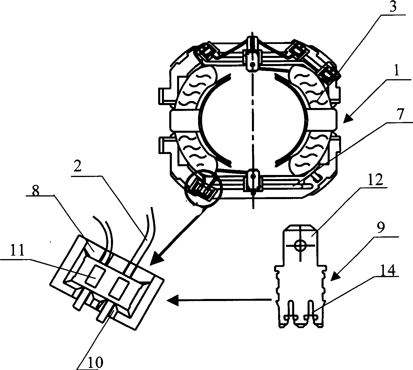
[0015] The connection structure of the enameled wire connection port and the connection terminal of the stator enameled wire of the vacuum cleaner motor according to the present invention will be described below with reference to the drawings and specific embodiments.

[0016] Such as figure 2 As shown, the connection structure between the enameled wire connection port and the connection terminal of the vacuum cleaner motor stator of the present invention includes a coil 3 wound by enameled wire 2 wound on the iron core of the stator 1, and an insulating frame 7, which connects two The connection port 8 and the connection terminal 9 of the above enameled wire 2; wherein the connection port 8 is arranged on the insulating frame 7, and in the connection port 8 and through both sides of the connection port 8, more than two can be formed. Through the wire groove hole 10 of the enameled wire 2, on the upper end surface of the connection port 8, at the position corresponding to the wi


PUM


Abstract

This invention relates to a connection structure of a port and a terminal of enamel wires for a dust collector motor stator including a coil winded on the stator core with the enamel wires, an insulation frame, a connection port and a terminal connecting more than two enamel wires, in which, the port is set on the insulation frame, more than two lead slot holes passing through the enamel wires are formed in the port and through both sides of the port, open-ends corresponding to the slot holes are formed on the top surface of the port, a conduction part is formed on the top of the terminal and over two grooves are formed on the bottom, the terminal is plugged into the open-end of the port to lacerate the foreskin of the enamel wires to be connected with each other via the connection terminal and conducted.

Description


Claims


Application Information

Patent Timeline
Owner LG ELECTRONICS (TIANJIN) APPLIANCES CO LTD
Why Eureka
Try Eureka