Method of realizing locomotive signal principalization using radio locomotive signal

A locomotive signal and signal machine technology, applied in signal transmission systems, radio transmission systems, electrical signal transmission systems, etc., can solve the problems of no signal in the side line fork area, non-uniform stations and sections, affecting the efficiency of vehicle control, etc. The effect of security and efficiency, high transmission reliability, and large amount of transmitted information

Inactive Publication Date: 2006-06-28
BEIJING JIAOTONG UNIV
View PDF0 Cites 18 Cited by
  • Summary
  • Abstract
  • Description
  • Claims
  • Application Information

AI Technical Summary

Benefits of technology

The invention improves how well trainers can communicate with vehicles on their own without having them have to be equipped for communication purposes or requiring special equipment like radio systems. It also allows trainsmen to see everything they are doing during training sessions more clearly than if there were no such devices at all. This makes it easier for trainers to stay focused while working alongside other drivers' cars that may require different types of data from those being trained.

Problems solved by technology

This patented describes two types of technology for controlling vehicles during travel operations. One method involves combining certain features like radio communication or transponder systems into one unit called a "controlled tractor". Another approach uses multiple units connected together to form a single entity called a “headset” controlled by the operator. These methods aim to provide better overall performance while maintaining good security measures against external influences. However, current solutions lack sufficient accuracy due to variations between individual components caused by differences in road surface quality and other environmental effects.

Method used


Image

  • Method of realizing locomotive signal principalization using radio locomotive signal
  • Method of realizing locomotive signal principalization using radio locomotive signal
  • Method of realizing locomotive signal principalization using radio locomotive signal

Examples


Embodiment Construction

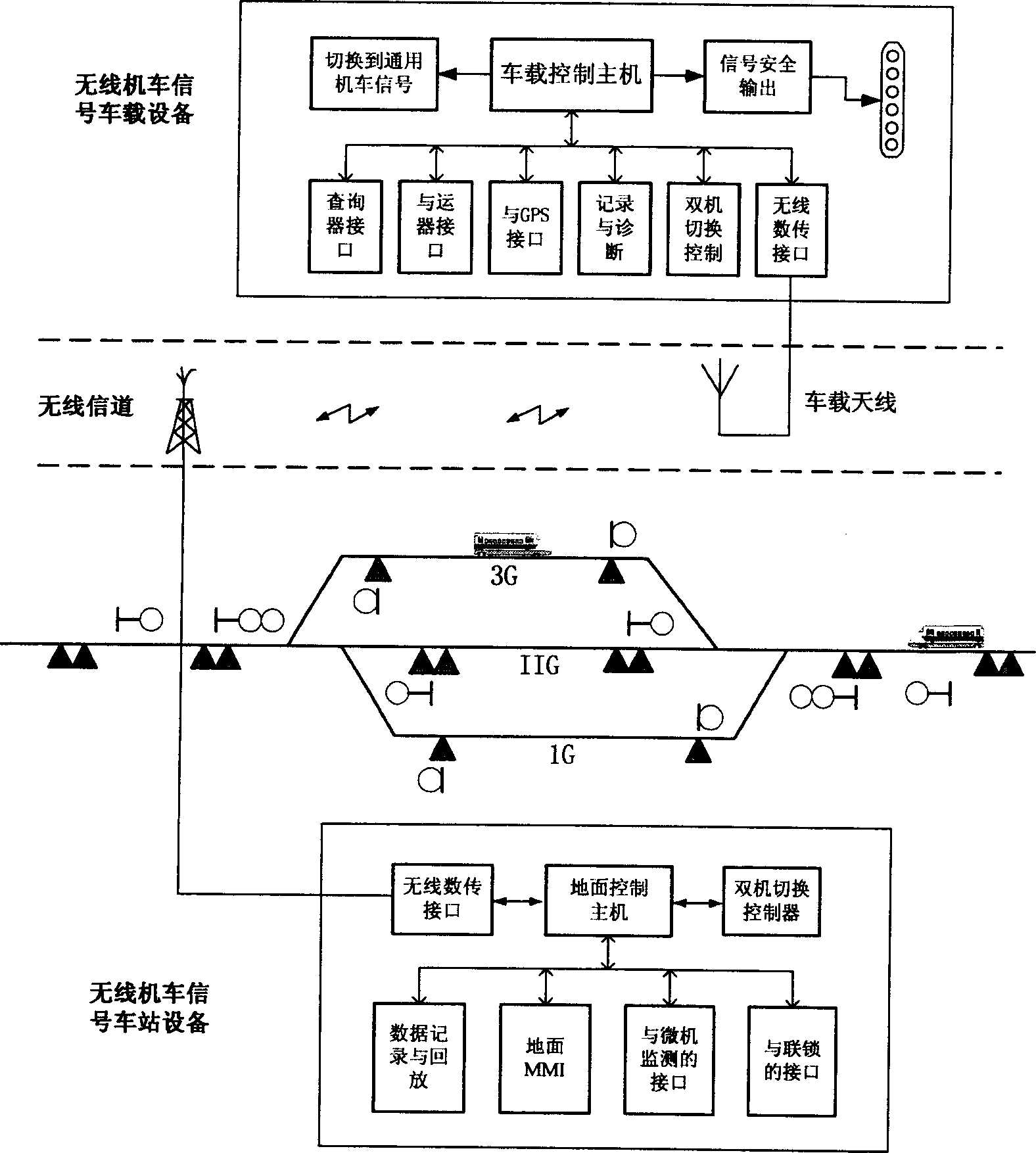
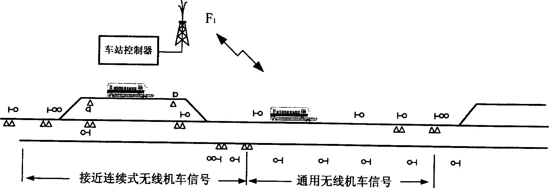
[0034] Existing wireless locomotive signaling systems can be divided into two types: the first type is that the locomotive signal is displayed during the whole running process of the train from one station to another station, which is called continuous locomotive signalling. This type has wireless signal field strength coverage in stations and sections, and is realized by continuous wireless transmission methods such as GSM-R or TETRA. The second type is that when the train is running from one station to another, it only has locomotive signal display near the station, which is called near continuous wireless locomotive signal. This type only has wireless signal field strength coverage around the station, so it is suitable for realization with ordinary digital radio stations. The main body scheme described in the present invention is suitable for semi-automatic occlusion and automatic occlusion intervals.

[0035] Such as figure 1 As shown, the wireless locomotive signal subject


PUM


Abstract

This invention discloses a method for realizing superior position of signals for locomotives , in which, a locomotive-carried digital transmission broadcast station and a station ground digital transmitted broadcast station are applied for the wireless locomotive signals to make up of a wireless channel so as to get signals and entry information from the chain interfaces directly to set up a corresponding relation between the train and entry combining with the train position to form signal information to be sent to the locomotive via the channel to be compared with the feedback signal to determine the effectiveness of the signals, which utterly breaks away from the restrict of railway circuit, interference of adjacent lines and half intrusion.

Description


Claims


Application Information

Patent Timeline
Owner BEIJING JIAOTONG UNIV
Why Eureka
Try Eureka