Computer interlock system

A computer interlocking and interlocking technology, which is applied in the direction of railway signal and safety, data exchange through path configuration, etc., can solve the problem that the bus signal is easily disturbed by the surrounding environment, the communication between the computer and the extension cannot be realized, and the correctness and accuracy cannot be guaranteed. Reliability and other issues, achieve good anti-interference performance, prevent electrical interference, and improve accuracy

Active Publication Date: 2006-07-19
CRSC RESEARCH & DESIGN INSTITUTE GROUP CO LTD
View PDF1 Cites 28 Cited by
  • Summary
  • Abstract
  • Description
  • Claims
  • Application Information

AI Technical Summary

Benefits of technology

This patented technology describes an electronic controlling unit that includes two parts: one part consists mainly of a CPU chip with memory for storing program instructions or other operational parameters; another part contains components like sensors and actuators attached to it by wires. These connections allow signals between them to be transmitted quickly without being affected by external factors such as lightning strikes or radio waves. Additionally, there may also include software modules called process managers on top of this circuit board where they manage communication over different networks. Overall, these technical features help ensure stable operation even at extreme environments while maintaining high efficiency.

Problems solved by technology

This patented technical problem addressed in this patents relates to improving the performance and safety of railways that use double machine Hot Standby redundancy structures for controllers. Current methods have limitations with regard to accurately gathering important information about each piece of equipment or managing operations during emergencies due to environmental factors like temperature changes and other external influences affecting signals transmitted through wires connecting them. Additionally, current techniques require manual testing before deploying new components can ensure their effectiveness over time.

Method used


Image

  • Computer interlock system
  • Computer interlock system
  • Computer interlock system

Examples


Embodiment Construction

[0021] Preferred embodiments of the present invention will now be described with reference to the accompanying drawings. However, the invention may be embodied in many different forms and should not be limited to the precise forms disclosed; rather, the examples given herein are intended to disclose the invention thoroughly and completely. , and fully convey the scope of the present invention to those skilled in the art.

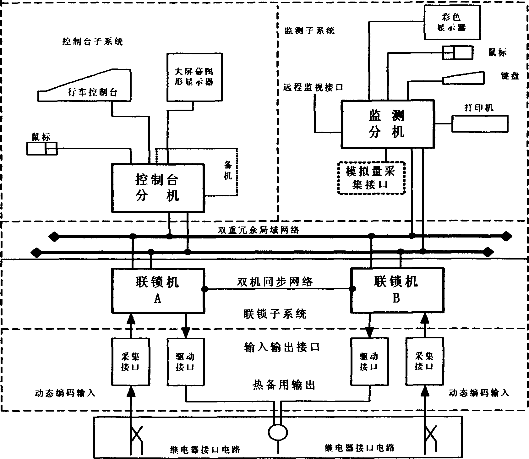
[0022] A computer interlocking system of the present invention is a dual-machine dynamic redundant hot standby system, and the two interlocking machines can be mutually active and standby machines. The interlock machine has three states: working state, hot standby state and cold machine state. The working mode of the dual machine is as follows: according to the starting sequence, the machine that is put into operation first is automatically the working machine, and the machine that is put into operation later is the hot standby machine. The working machine au


PUM


Abstract

The invention discloses a computer interlocking system DS 6-11, which comprises the following parts: control platform subsystem, interlocking subsystem, input subsystem, output subsystem, monitor subsystem and network communication subsystem to connect each subsystem, wherein the system possesses high reliable industrial control computer and imbedded CPU control system, which applies network communication technique to constitute the distribution-typed control system. The invention realizes self-detecting function for output and input circuit, which reinforces the interference-proof and stability property greatly.

Description


Claims


Application Information

Patent Timeline
Owner CRSC RESEARCH & DESIGN INSTITUTE GROUP CO LTD
Why Eureka
Try Eureka