Quantitative analyzing method for crystalline phase cobalt oxide content in lithium cobalt oxide
A technology of lithium cobalt oxide and cobalt oxide, which is applied in the direction of material analysis using radiation diffraction, material analysis, and material analysis using wave/particle radiation, which can solve the problem of indetermination of the crystal phase structure of cobalt oxide and accurate inference results gender issues
- Summary
- Abstract
- Description
- Claims
- Application Information
AI Technical Summary
Problems solved by technology
Method used
Image

Examples
Example Embodiment
[0050] Example 1 This example illustrates the method provided by the present invention.
[0051] XRD diffractometer used: D / MAX2200PC XRD diffractometer produced by Rigaku Corporation;
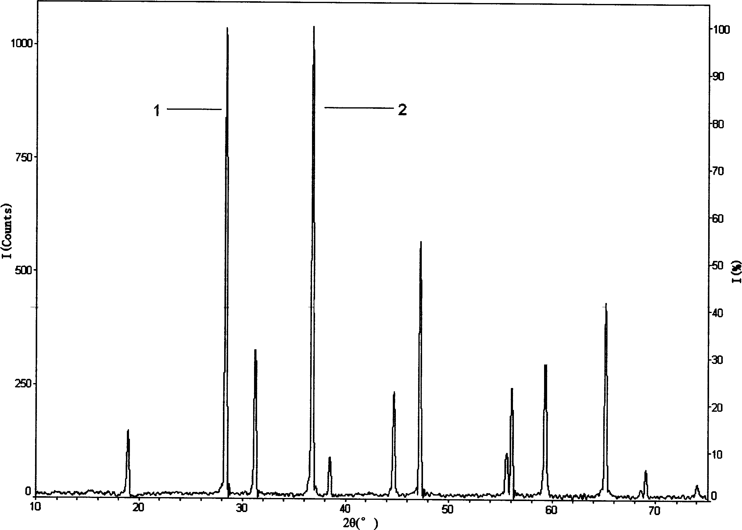
[0052] The measurement conditions of the XRD diffractometer include: the wavelength of the X-ray source λ=1.54056 angstroms (Cu / Kα1), the use power of the copper target is 40 kV, 20 mA (ie 800 watts); graphite monochromator; goniometer The scanning speed is 4° / min, the scanning range is 2θ=10°-75°, the scanning step diameter is 0.020° / step, and the scanning mode is θ / 2θ linked scanning; the optical path slit system parameter setting: divergence slit is 1 o , The anti-scatter slit is 10 mm, the variable slit is automatically adjusted by the instrument, and the receiving slit is 0.3 mm;
[0053] The instrument data processing software is: MDI-JADE (5.0);
[0054] Internal standard substance: Si powder with a purity of 99% by weight, produced by Sigma-aldrich, USA;
[0055] Standard material:
Example Embodiment
[0086] Embodiment 2 This embodiment illustrates the method provided by the present invention.
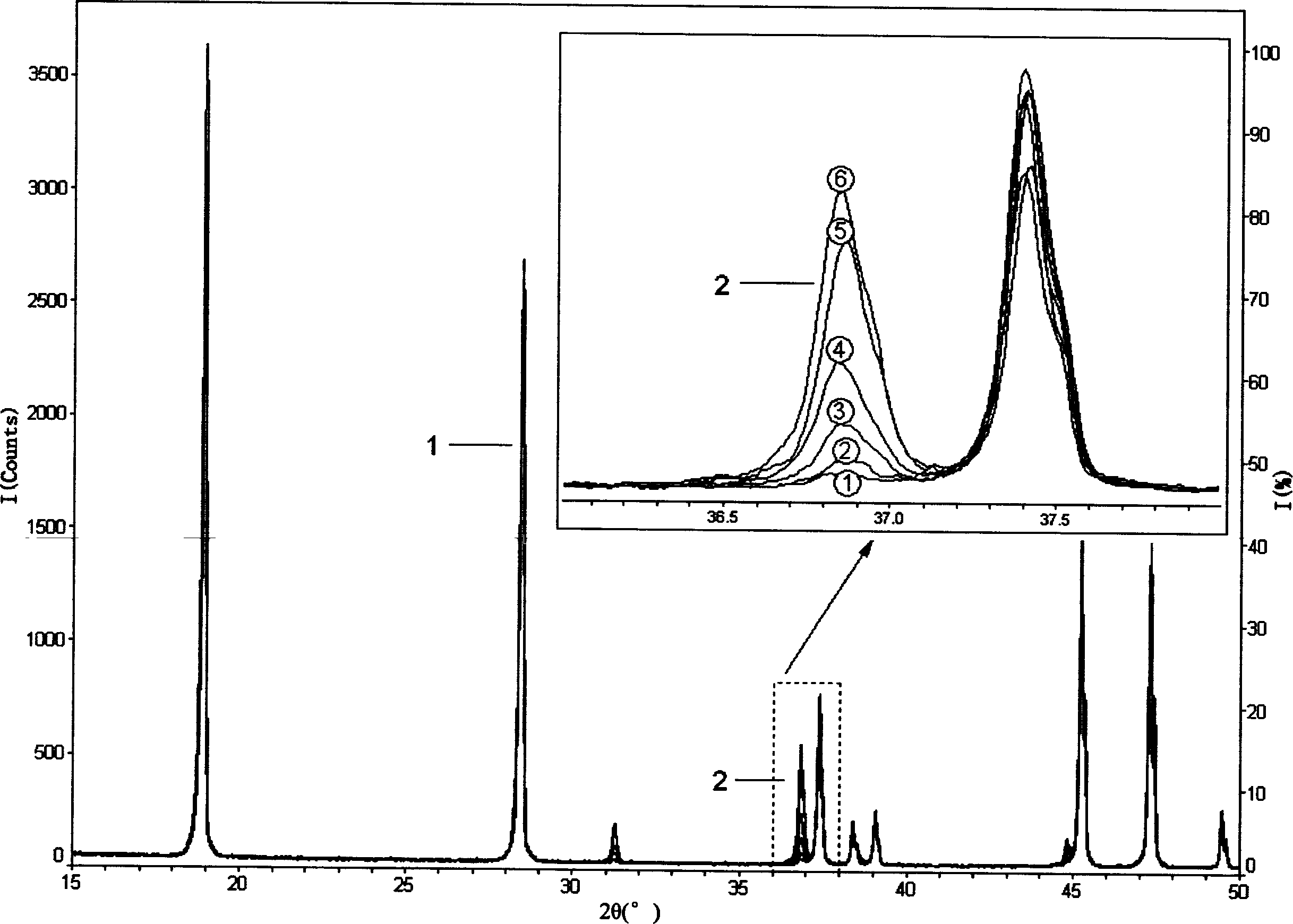
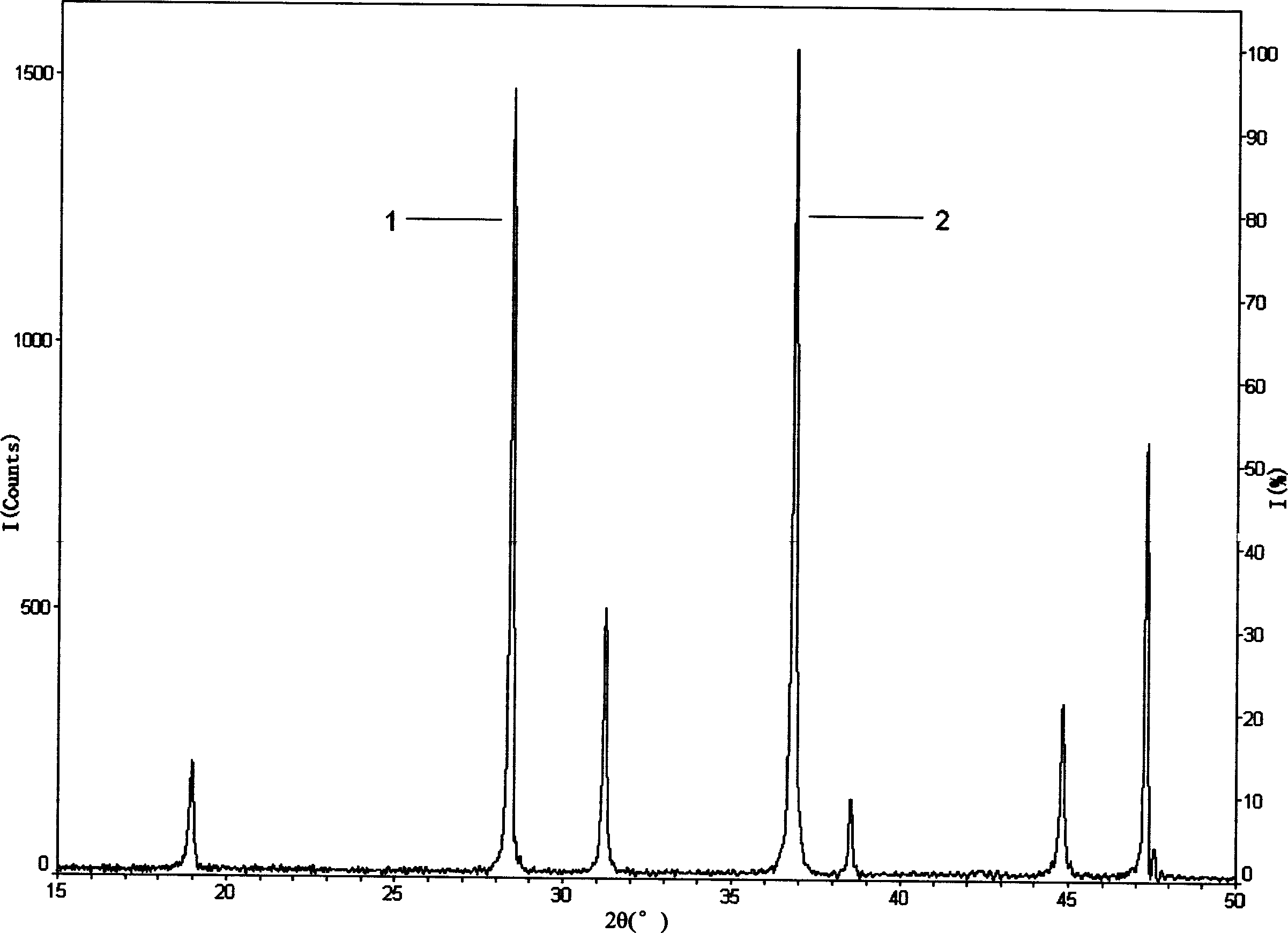
[0087] Repeat the steps of Example 1 above to determine Co 3 O 4 The content is 1%, 2%, 5%, 10%, 20%, 25% LiCoO 2 Crystal phase Co in powder 3 O 4 The difference is that the power of the XRD diffractometer is 1600 watts, the scanning speed of the goniometer is 2 degrees / minute, the scanning range 2θ=15°-50°, and the scanning step diameter is 0.010 degrees / step; step (1 )Medium Si powder internal standard substance and Co 3 O 4 Average particle size D of the mixture of standard materials 50 = 7.357 microns; the measured XRD diffraction spectrum is as follows image 3 As shown, the integrated intensity I of the strongest diffraction peak 1 of the internal standard material Si powder (内标) = 20906 (Counts), Co 3 O 4 The integrated intensity I of the strongest diffraction peak 2 of the reference material (标准物质) = 27268 (Counts); coefficient K = 0.6522; step (2) contains crystal phase Co 3 O
Example Embodiment
[0095] Example 3 This example illustrates the method provided by the present invention.
[0096] Repeat the steps of Example 1 above to determine the content of crystalline CoO in lithium cobalt oxides with 5%, 10%, 20%, 30% and 40% crystalline CoO content. The differences are:
[0097] The measurement conditions of the XRD diffractometer: the same as in Example 2;
[0098] Internal standard substance: average particle size D 50 = 9.440 microns, 99% pure crystalline NaCl powder;
[0099] Standard material: crystalline CoO powder with an average particle size of D50=3.462 microns and a purity of 99% by weight;
[0100] n=1, n o =1;
[0101] Average particle size D of the mixture of NaCl powder internal standard material and CoO standard material 50 =2.430 microns;
[0102] Lithium oxide: LiCoO without NaCl and / or CoO crystal phase 2 powder;
[0103] The XRD diffraction spectrum obtained in step (1) is as follows Figure 5 As shown, the integrated intensity I of the strongest diffrac
PUM
| Property | Measurement | Unit |
|---|---|---|
| The average particle size | aaaaa | aaaaa |
| The average particle size | aaaaa | aaaaa |
| The average particle size | aaaaa | aaaaa |
Abstract
Description
Claims
Application Information
 - R&D Engineer
- R&D Manager
- IP Professional
- Industry Leading Data Capabilities
- Powerful AI technology
- Patent DNA Extraction
Browse by: Latest US Patents, China's latest patents, Technical Efficacy Thesaurus, Application Domain, Technology Topic.
© 2024 PatSnap. All rights reserved.Legal|Privacy policy|Modern Slavery Act Transparency Statement|Sitemap