Variable capacity rotary compressor

A rotary compressor and compressor technology, applied in the direction of rotary piston machines, rotary piston pumps, rotary piston/swing piston pump components, etc., can solve problems such as wear on the outer surface of the rollers

Inactive Publication Date: 2007-03-21
SAMSUNG ELECTRONICS CO LTD
View PDF1 Cites 0 Cited by
  • Summary
  • Abstract
  • Description
  • Claims
  • Application Information

AI Technical Summary

Problems solved by technology

[0003] However, since the blades in contact with the rollers of this rotary compressor are separated into first blades and second blades, the outer

Method used


Image

  • Variable capacity rotary compressor
  • Variable capacity rotary compressor
  • Variable capacity rotary compressor

Examples


Embodiment Construction

[0018] Hereinafter, preferred embodiments provided according to the present invention will be described in detail with reference to the accompanying drawings.

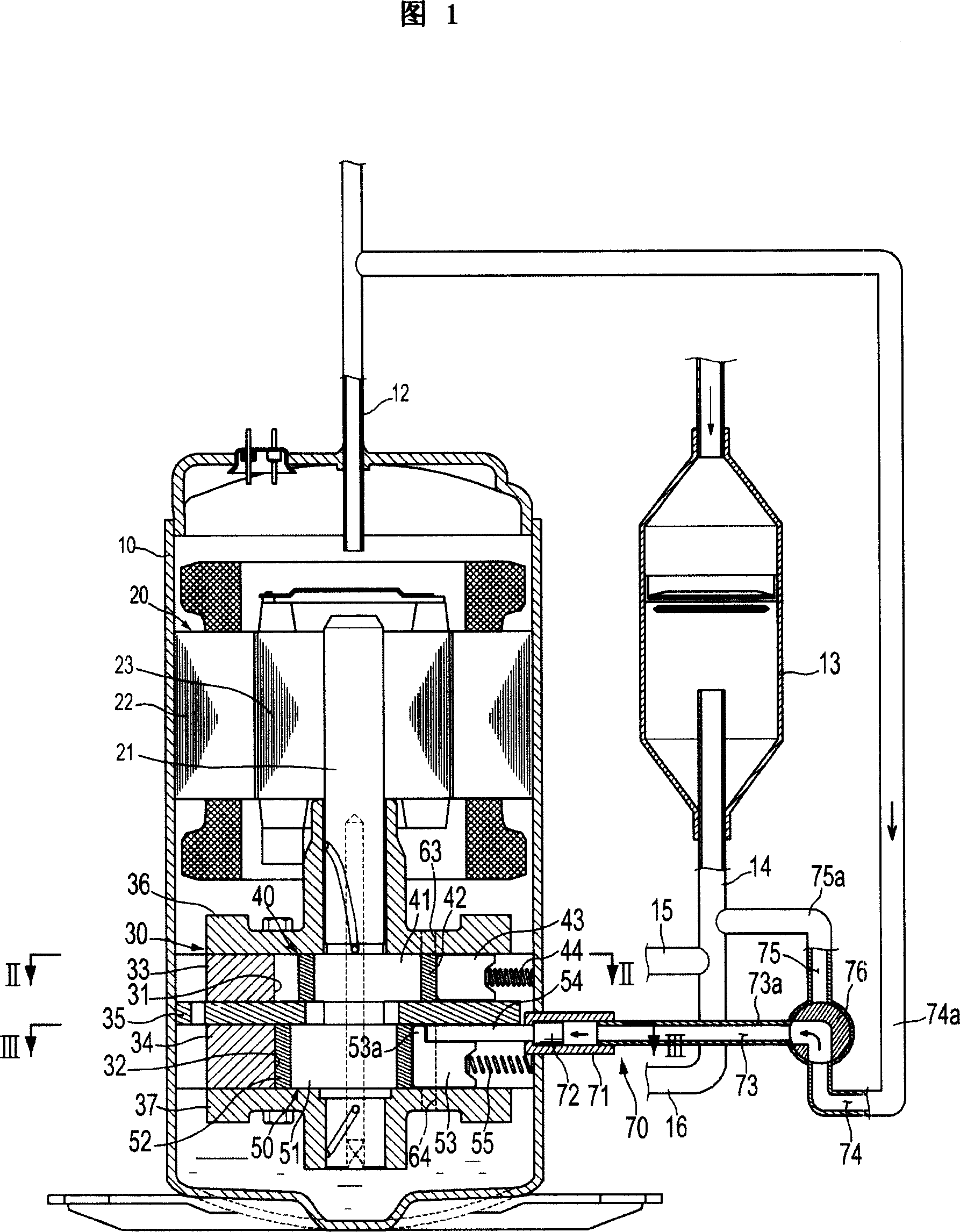
[0019] 1 to 5 show a variable capacity rotary compressor according to a first embodiment of the present invention. The variable capacity rotary compressor of the first embodiment, as shown in FIG. agency30.

[0020] The electric mechanism 20 includes a cylindrical stator 22 fixed on the inner surface of the sealed container 10 , and a rotor 23 rotatably disposed inside the stator 22 and coupled to the rotating shaft 21 at its center. Such a motor mechanism 20 rotates a rotor 23 when power is applied, and the rotor 23 in turn causes the rotation shaft 21 to rotate, thereby driving the compression mechanism 30 .

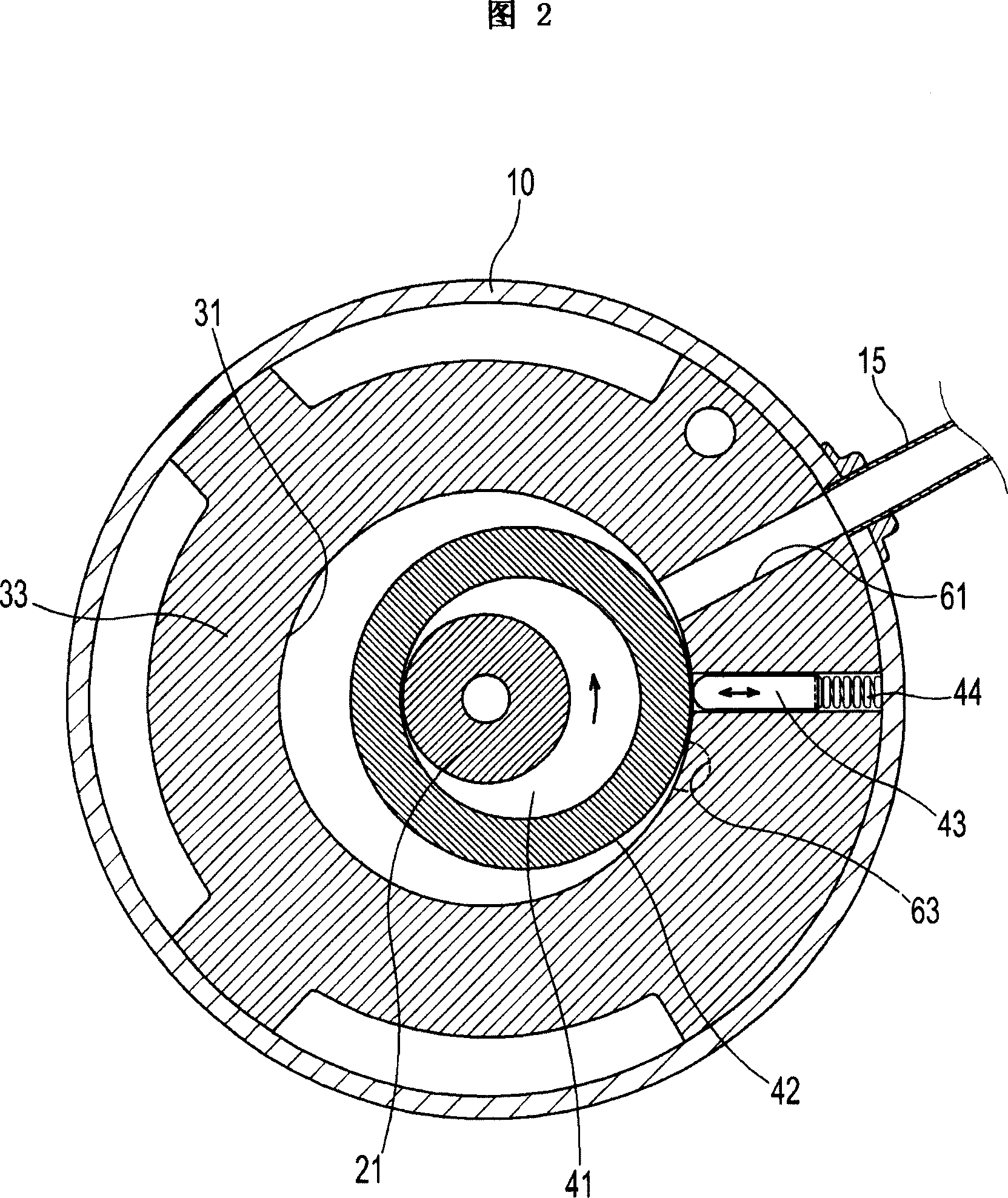
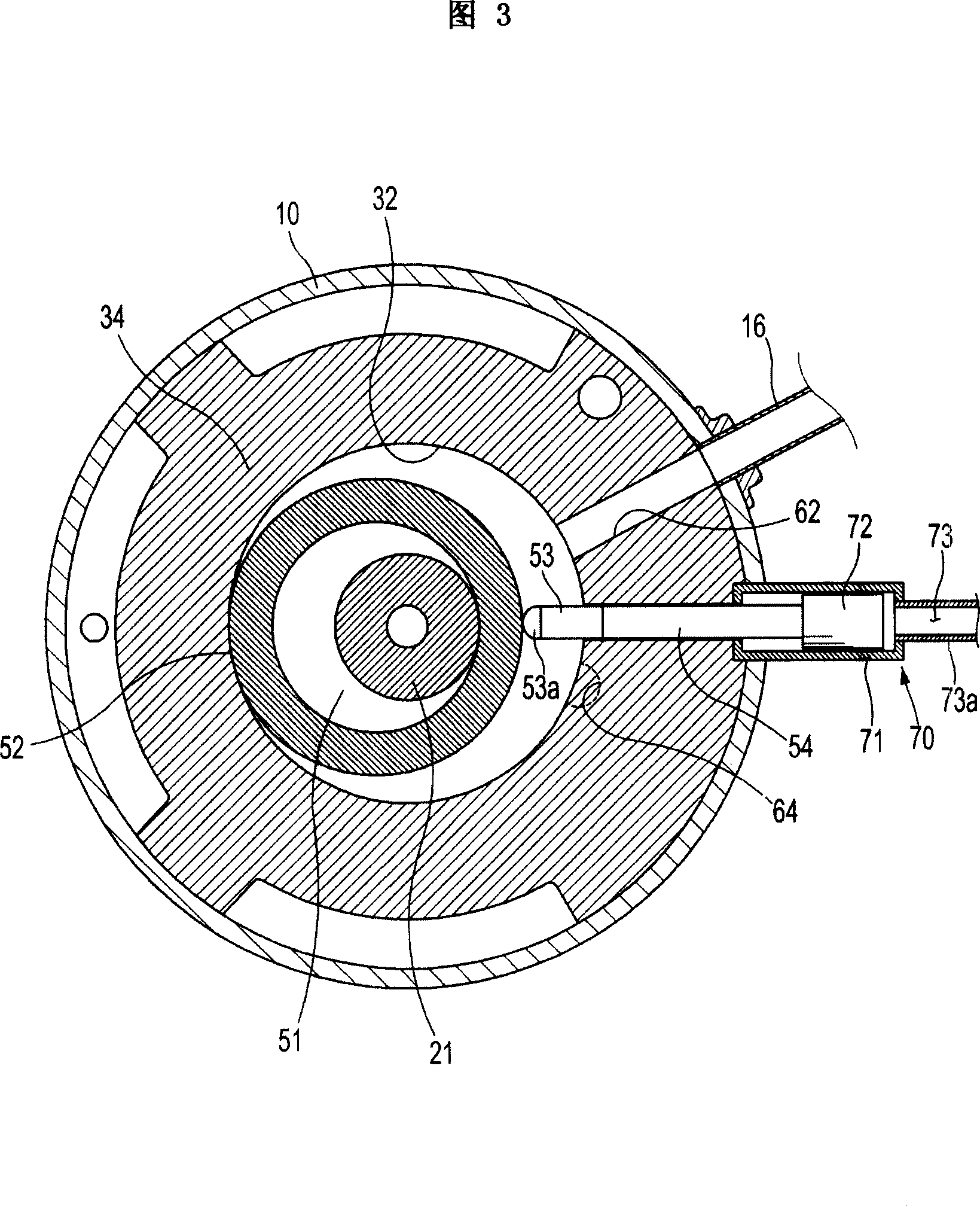
[0021] As shown in FIGS. 1 to 3 , the compression mechanism 30 includes an outer shell having a first compression chamber 31 and a second compression chamber 32 divided from each other, and housings respectively


PUM


Abstract

The invention discloses a variable capacity rotary compressor capable of preventing severely wearing of a roller exterior surface. The variable capacity rotary compressor comprises crusts of a first and second compressing chambers which are divided by each other; a first and second rollers arranged respectively inside the first and second compressing chambers; a first vane for setting off the first compressing chamber according to a radial advancing and retreating of the first roller; a second and third vanes slidely supported with each other for setting off the second compressing chamber according to a radial advancing and retreating of the second roller; a vane controller for restricting or releasing the third vane and for controlling the compressing volume; wherein the second vane comprises an extension part extended for covering a front end of the third vane.

Description


Claims


Application Information

Patent Timeline
Owner SAMSUNG ELECTRONICS CO LTD
Why Eureka
Try Eureka