A slow-moving comparator

A hysteresis comparator and comparator technology, applied in multiple input and output pulse circuits, etc., can solve problems such as hysteresis and not necessarily symmetrical

Inactive Publication Date: 2007-05-23
HUAZHONG UNIV OF SCI & TECH
View PDF0 Cites 7 Cited by
  • Summary
  • Abstract
  • Description
  • Claims
  • Application Information

AI Technical Summary

Benefits of technology

This patented technology improves on existing circuits that use negative feedback loops for achieving hysteretic behavior. It uses this method to generate specific voltages at certain points within the circuit's input range based upon their previous values or changes over time. These techniques help improve accuracy when comparing small amounts of data accurately compared against large ones.

Problems solved by technology

This patented technical problem addressed in this patents relates to improving the performance (reliableness) or functionality of an integrating chip's own protective and detection systems used during operation without causing any damage on other parts within their protected area.

Method used


Image

  • A slow-moving comparator
  • A slow-moving comparator
  • A slow-moving comparator

Examples


Embodiment Construction

[0015] The following will illustrate through typical application examples in conjunction with the accompanying drawings.

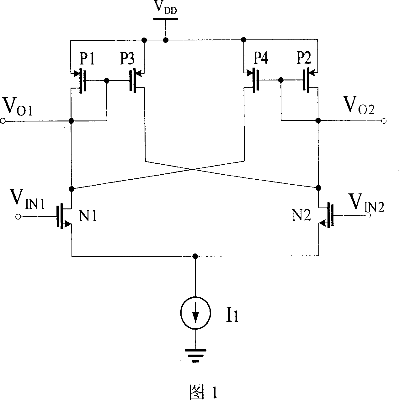
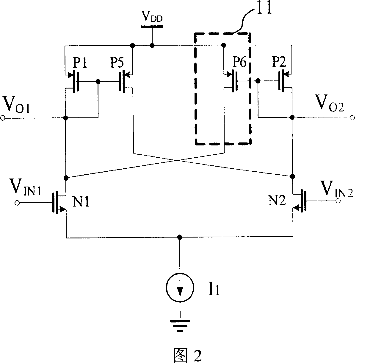
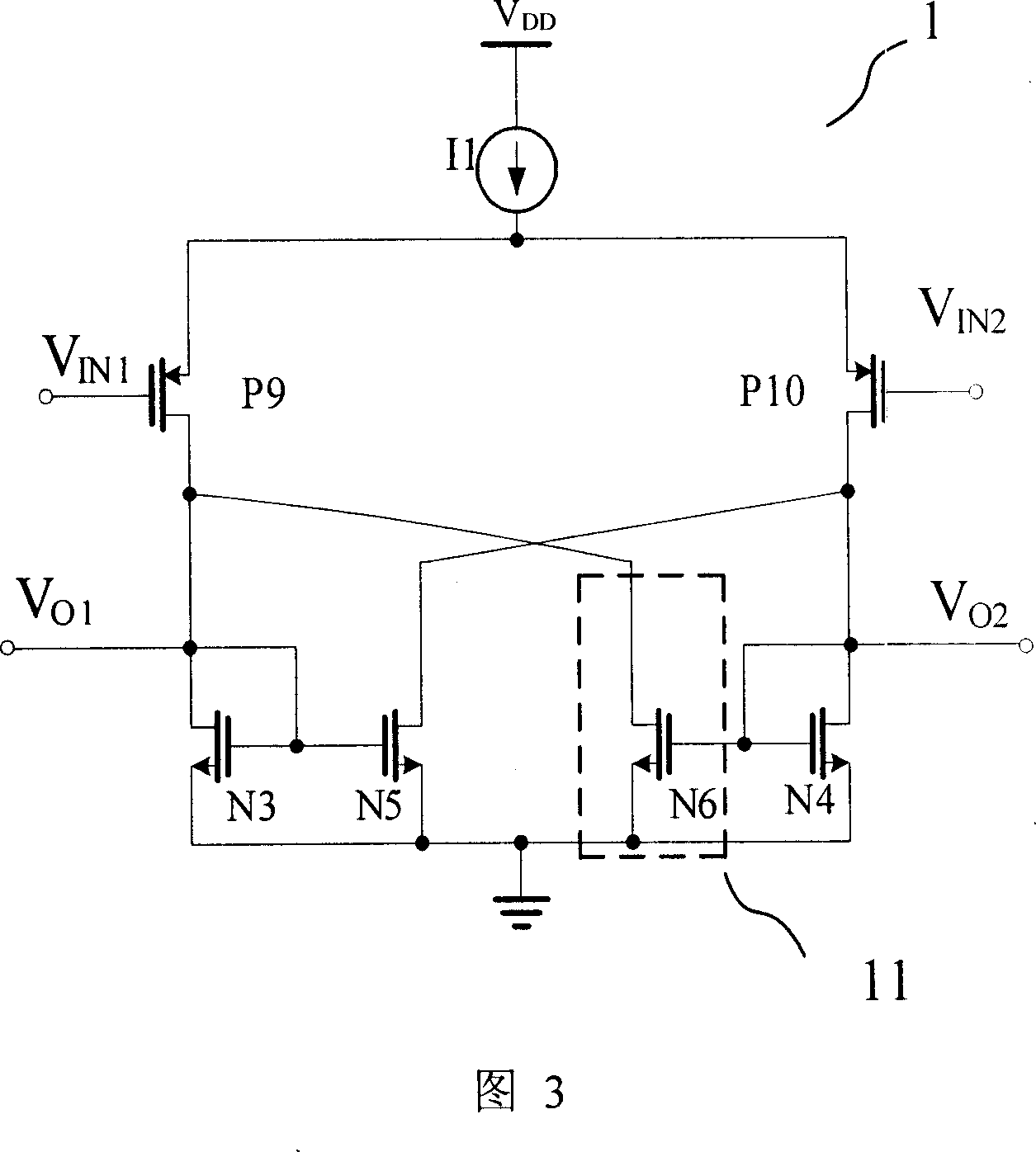
[0016] The hysteresis comparator of the present invention includes a current source I1, two input MOS transistors, three load MOS transistors and a hysteresis regulator 11, wherein the hysteresis regulator 11 is used to adjust the threshold of the comparator. When the input MOS tube is an NMOS tube, the load MOS tube is a PMOS tube; when the input MOS tube is a PMOS tube, the load MOS tube is an NMOS tube.

[0017] When the input MOS transistor is an NMOS transistor, the load MOS transistor is a PMOS transistor, and the hysteresis regulator 11 is realized by using a PMOS transistor P6, the specific structure of the circuit is shown in FIG. 2 . The NMOS transistors N1 and N2 in the circuit are completely symmetrical. Width to length ratio of P1, P2, P5 (W / L) P1 , (W / L) P2 , (W / L) P5 Equal, ie (W / L) P1 =(W / L) P2 =(W / L) P5 =A; and the width-to


PUM


Abstract

The invention relates to a lagging comparer, wherein it comprises current source I1, two input MOS tubes, three load MOS tubes, and lagging adjuster for adjusting the threshold value of comparer. When the input MOS tube is NMOS tube, the load MOS tube uses PMOS tube; the single threshold value of circuit is irrelative to the circuit element parameters, that one fixed input voltage of comparer can fix single threshold value; the inventive circuit has asymmetry positive feedback circuit to form the lagging circuit of lagging comparer, to generate threshold voltage and complete comparison. The invention also has positive feedback branch and output branch, MOS tube with static protection and resistance.

Description


Claims


Application Information

Patent Timeline
Owner HUAZHONG UNIV OF SCI & TECH
Why Eureka
Try Eureka