Anti-Static Sole

a technology of anti-static soles and soles, applied in the field of shoes, can solve the problems of high cost, high static charge on the user, and damage to precision equipment such as electronic elements or magnetic memory cards, so as to avoid the damage of resistors, reduce static charge, and save costs

Inactive Publication Date: 2010-08-19
NEW PROCESS CORK
View PDF12 Cites 7 Cited by
  • Summary
  • Abstract
  • Description
  • Claims
  • Application Information

AI Technical Summary

Benefits of technology

The technical effect of this patented invention is to create an antistatic shoe without metal wires exposure or damage caused by the use of a chip resistor instead of a ceramic resistor for static charge reduction. This eliminates the need for external frames and saves money compared to traditional shoes made up of plastic soles.

Problems solved by technology

This patent describes a problem where static electrical charges may occur during use of electronic devices like computers or magnetic memories. These charges can harm sensitive components like sensing chips used in these systems. To solve this issue, there have been developed various methods to prevent static charges from affecting these components. However, current methods require expensive materials and complicated manufacturing techniques, making them difficult to implement.

Method used


Image

  • Anti-Static Sole
  • Anti-Static Sole
  • Anti-Static Sole

Examples


Embodiment Construction

[0023]The present invention will be clearer from the following description when viewed together with the accompanying drawings, which show, for purpose of illustrations only, the preferred embodiment in accordance with the present invention.

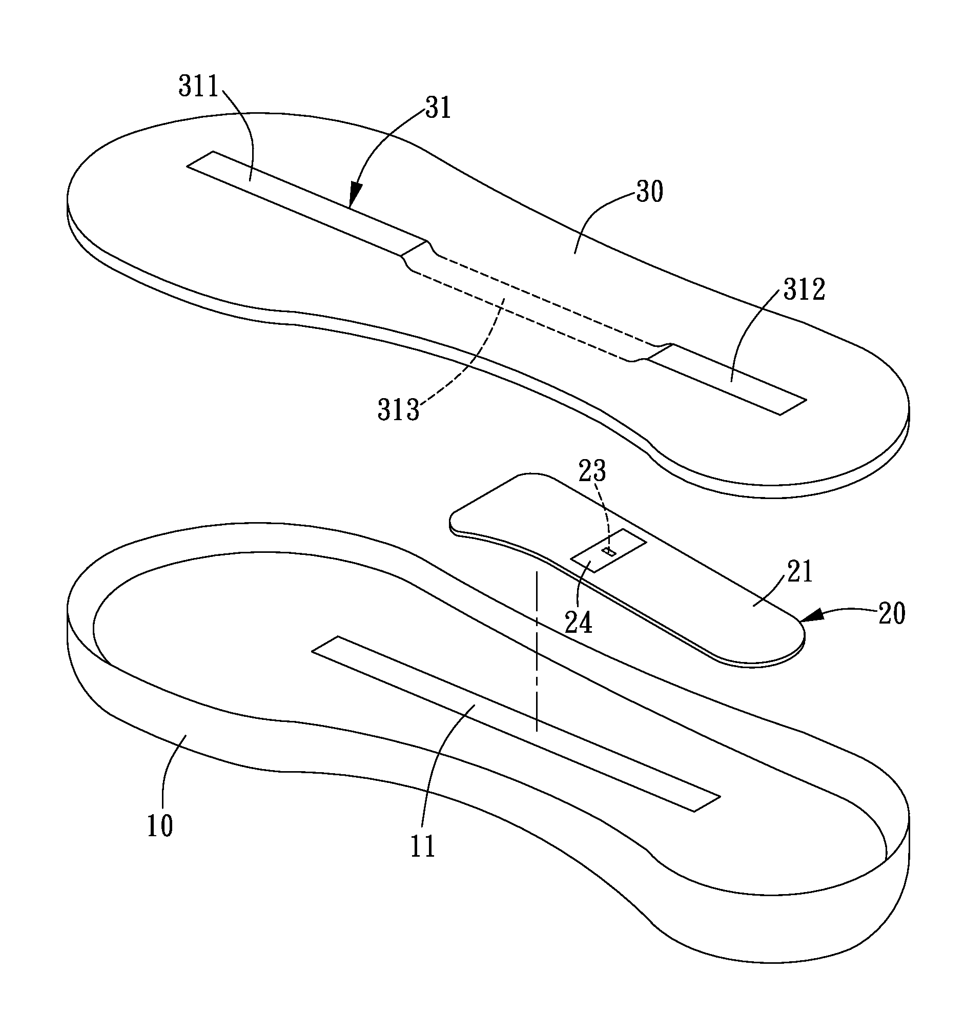
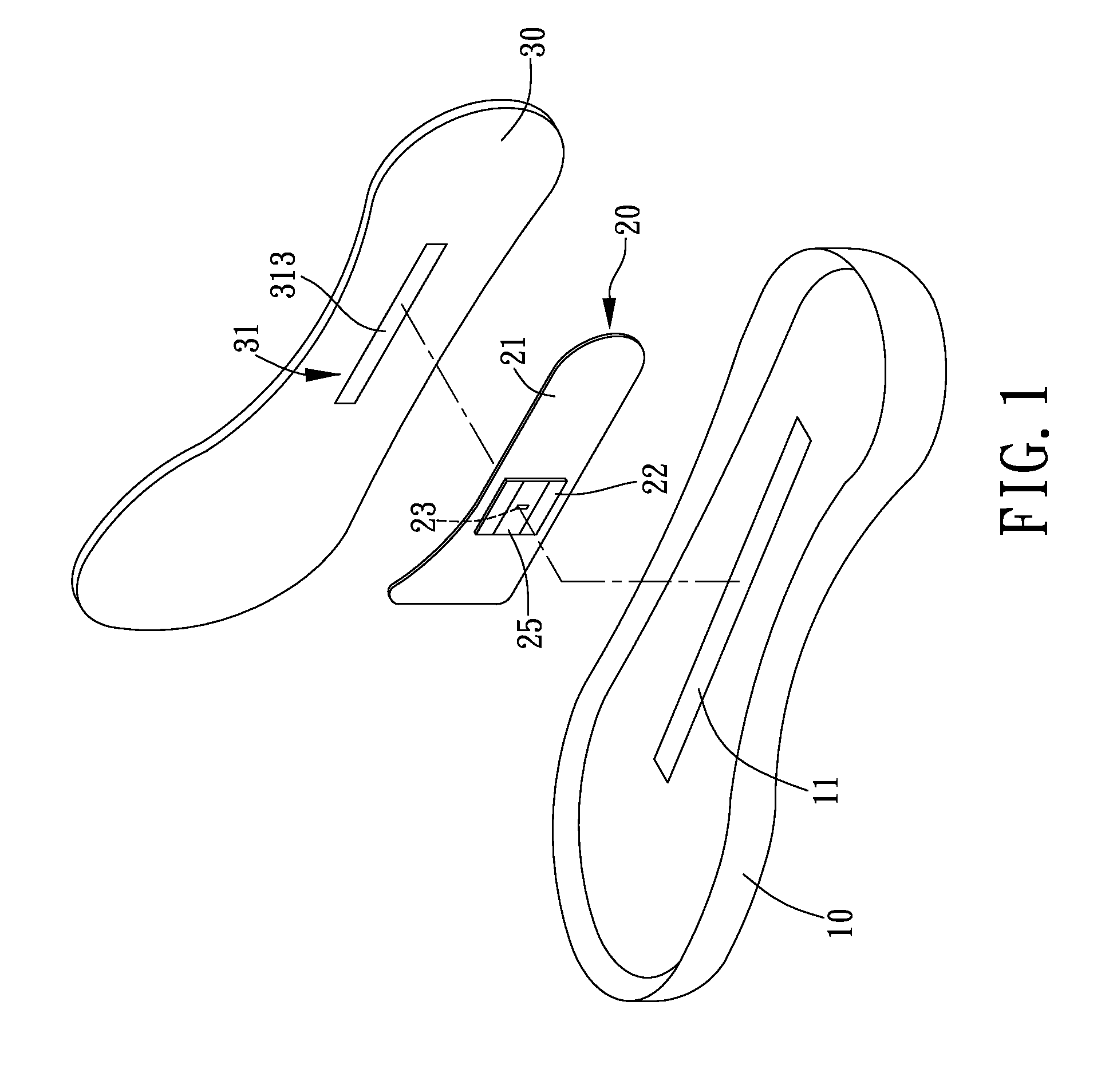
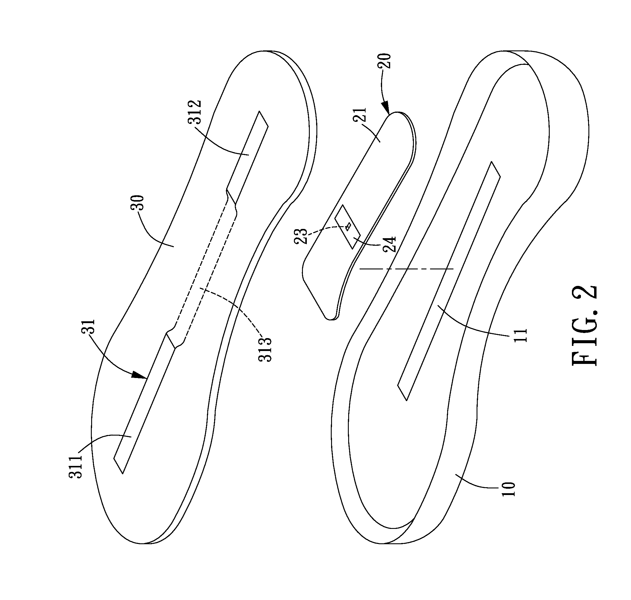
[0024]Referring to FIGS. 1-4, an anti-static sole in accordance with the present invention comprises a midsole 10, a pad body 20, and an insole 30.

[0025]The midsole 10 is made of conductive material and provided with a first conductive element 11. The first conductive element 11 is made of conductive fabric formed by mixed weaving of fiber and wires, so the wires can be used to conduct electricity. The first conductive element 11 is exposed from a top surface of the midsole 10.

[0026]The pad body 20 has a bottom surface disposed at the top surface of the midsole 10. The pad body 20, as shown in FIG. 3a, includes a main pad 21, an assistant pad 22, a chip resistor 23, an upper conductive fabric 24 and a lower conductive fabric 25. The main pad 21 incl


PUM


Abstract

An anti-static sole is provided with a pad body between a midsole and an insole. In the pad body is provided a chip resistor. The chip resistor includes a connecting pin at each of two opposite ends thereof. The two connecting pins of the chip resistor are electrically connected to the insole and the midsole, respectively. Since the chip resistor has no exposed wires, damage to the wires is avoided. Further, the anti-static effect can be improved since the resistance of the chip resistor is stable.

Description


Claims


Application Information

Patent Timeline
Owner NEW PROCESS CORK
Why Eureka
Try Eureka