Modified eddy current probe having a faraday shield

a technology of faraday shield and eddy current probe, which is applied in the field of modified eddy current probes, can solve the problems of inaccurate distance measurement, inability of known sensors to monitor and analyze, and inability to measure the distance to low conductivity materials, etc., to achieve accurate monitoring, analysis, and measurement

Active Publication Date: 2019-06-25
CENTRUS ENERGY CORP
View PDF5 Cites 0 Cited by
  • Summary
  • Abstract
  • Description
  • Claims
  • Application Information

AI Technical Summary

Benefits of technology

The present innovation improves on existing eddy-current probes by adding certain features like better sensing capabilities for detecting small objects made up mostly of carbon materials with very high electrical resistances called graphene. This helps improve accuracy when measuring distances without affecting their ability to transmit signals effectively through them.

Problems solved by technology

The technical problem addressed in this patented text is how to improve the accuracy and efficiency of measuring distances between electrified targets made up of different types of materials like metal while minimizing interference due to their proximity to other nearby sources.

Method used


Image

  • Modified eddy current probe having a faraday shield
  • Modified eddy current probe having a faraday shield
  • Modified eddy current probe having a faraday shield

Examples


Embodiment Construction

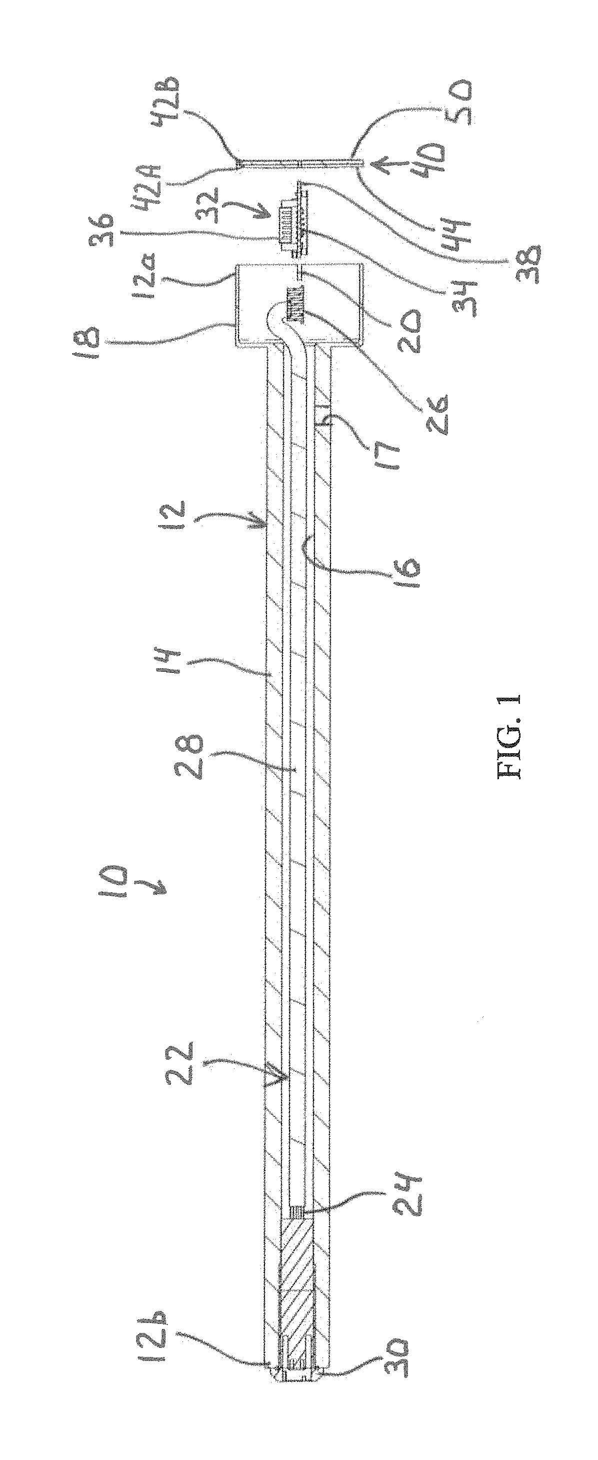
[0019]Referring now to the drawings, there is illustrated in FIG. 1 the structure of an improved or modified eddy current (MEC) probe 10 in accordance with this invention. The MEC probe 10 includes a probe body 12 having a first end 12a and a second end 12b. The probe body 12 has an elongated, substantially cylindrical stem 14 defining a longitudinally extending bore 16 formed therein. A hole 17, the purpose for which is described below, may be formed in the stem 14. The second end of the probe body 12 defines a cup 18. Longitudinally extending notches 20 are formed in a wall of the cup 18. The probe body 12 may be formed from brass. Alternatively, the probe body 12 may be formed from other metals, such as copper, metal alloys, and other conductive material.

[0020]In the illustrated embodiment, the stem 14 has an outside diameter of about 0.625 inches. Alternatively, the stem 14 may have any other desired diameter, such as a diameter within the range of about 0.50 inches to about 0.75 i


PUM


Abstract

A modified eddy current (MEC) probe includes a probe body having a bore formed therein. A printed circuit board (PCB) assembly includes a circuit board defining a plane, has a plurality of electronic components mounted thereon, and is configured for mounting within the bore of the probe body. A coil board assembly is electrically connected to the PCB assembly, defines a plane, and includes a first coil board layer, a second coil board layer bonded to the first coil board layer, a transmitter coil formed on an outside surface of the first coil board layer, a Faraday shield formed on an outside surface of the second coil board layer, and a sensor coil formed on one of an inside surface of the first coil board layer and the second coil board layer, such that the sensor coil is positioned between the first coil board layer and the second coil board layer. The plane of the coil board assembly is arranged orthogonally to the plane of the circuit board.

Description


Claims


Application Information

Patent Timeline
Owner CENTRUS ENERGY CORP
Why Eureka
Try Eureka