Electrical insider fitting for internal connection of flexible metal conduit to an electrical box

a technology of flexible metal conduit and electrical box, which is applied in the direction of electrical cable installation, electrical apparatus, cable installation apparatus, etc., can solve the problems of extended time for removing and reinstalling drywall, replacing or repairing wall surfaces, and conventional electrical fittings are not ideally suited for connection

Active Publication Date: 2019-10-01
ARLINGTON INDS
View PDF38 Cites 3 Cited by
  • Summary
  • Abstract
  • Description
  • Claims
  • Application Information

AI Technical Summary

Benefits of technology

The technical effect of this invention relates to making it easier for people who want to connect or disconnect electric wires without having to replace them with new ones after they have been installed on their walls.

Problems solved by technology

The technical problem addressed by this patented solution is how to secure flexible metallic conductors (such as copper) into an electricity socket without requiring removal after installation while also allowing it to still function properly when connecting wires through existing walls.

Method used


Image

  • Electrical insider fitting for internal connection of flexible metal conduit to an electrical box
  • Electrical insider fitting for internal connection of flexible metal conduit to an electrical box
  • Electrical insider fitting for internal connection of flexible metal conduit to an electrical box

Examples


Embodiment Construction

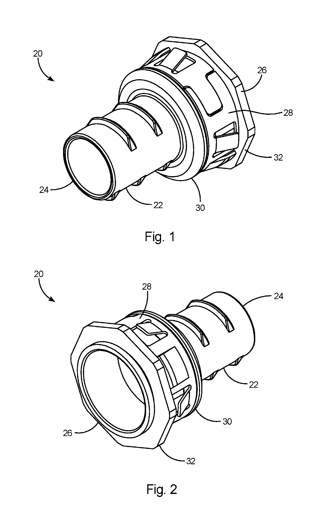
[0028]With reference to FIGS. 1 and 2, the present invention comprises an electrical insider fitting 20 for connecting flexible electrical conduit to an electrical box. The insider fitting 20 includes a tubular connector body 22 having a leading end 24 and a trailing end 26. The term “leading end” as used herein refers to the end of the fitting that is inserted through the access hole in an electrical box and the term “trailing end” refers to the opposing end of the fitting that is not inserted through the access hole of the electrical box. A snap ring 28 is disposed between the mid-body flange 30 and trailing flange 32 on the connector body 22.

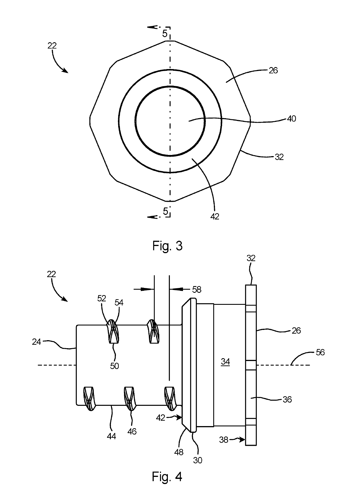
[0029]Referring to FIGS. 3 and 4, the mid-body flange 30 and trailing flange 32 define a seat 34 at the trailing end 26 of the connector body 22. Trailing flange 32 includes a plurality of flats 36 on its outer edge and an abutment surface 38. A leading bore 40 extends through the connector body and an inner abutment surface 42 surrounds the lea


PUM


Abstract

An electrical insider fitting for connecting flexible metal conduit to an electrical box without disrupting the walls surrounding the box. The fitting includes a connector body with a leading end, a trailing end, and a nose portion. A resilient split snap ring on the fitting enables snap connection of the fitting to the interior wall of an electrical box. Discontinuous threads on the nose portion are adapted to grab and hold a flexible metal conduit to the box. Conductors from the attached flexible metal conduit feed through the interior bores of the fitting to the interior of the electrical box enabling an installer to complete electrical connections in order to supply voltage to any components within the box.

Description


Claims


Application Information

Patent Timeline
Owner ARLINGTON INDS
Why Eureka
Try Eureka