Distributed beamforming system with user side beamforming processing

Active Publication Date: 2021-04-13
THE BOEING CO
View PDF10 Cites 0 Cited by
  • Summary
  • Abstract
  • Description
  • Claims
  • Application Information

AI Technical Summary

Benefits of technology

This patented technology allows for multiple devices (such as smartphones) connected wirelessly together through their own base station device called the Platform Terminal®. These connections can be used to send different types of messages like email, social media updates, etc., without being limited due to physical constraints such as wires between them.

Problems solved by technology

The technical problem addressed in this patents relates to improving wireless communication networks with beam forming technology (BF) without increasing their complexity. Specifically, existing methods involve both on- board and gateways based techniques such as grid network coding and fixed base stations. These approaches can lead to increased costs due to added equipment needed near each location where signals must travel through them.

Method used


Image

  • Distributed beamforming system with user side beamforming processing
  • Distributed beamforming system with user side beamforming processing
  • Distributed beamforming system with user side beamforming processing

Examples


Embodiment Construction

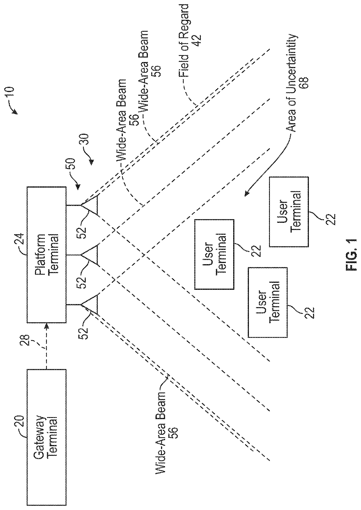
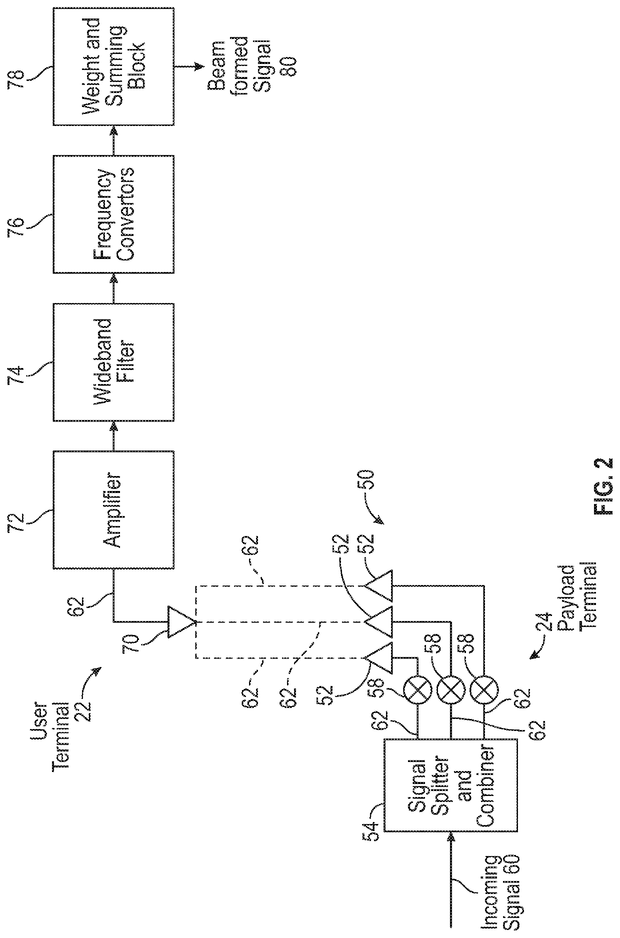
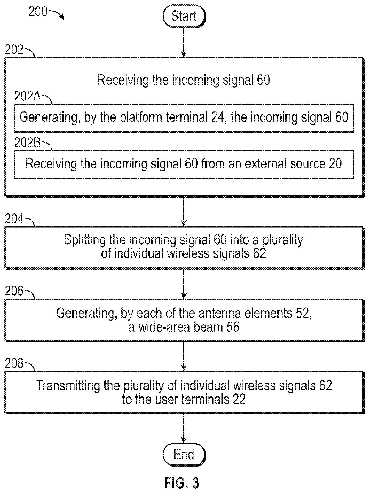
[0015]The present disclosure is directed to a distributed beamforming system including a plurality of user terminals and a platform terminal. The platform terminal includes an antenna array having a plurality of antenna elements, where each antenna element emits a wide-area beam that encompasses all of the user terminals that are part of the distributed beamforming system. The platform terminal transmits a plurality of individual wireless signals that are orthogonal with respect to one another based on frequency, time, or by coding techniques. It is to be appreciated that there is a one-to-one mapping of each individual wireless signal to each of the antenna elements located on the platform terminal. The individual wireless signals are received by each individual user terminal. The user terminals apply an amplitude weight and a phase shift to each of the individual wireless signals. The individual wireless signals are then combined together at the individual user terminals to generate


PUM


Abstract

A distributed beamforming system includes a platform terminal and a plurality of user terminals. The platform terminal includes an antenna array including a plurality of antenna elements. Each antenna element transmits a wide-area beam configured to encompass each of the plurality of user terminals. The platform terminal also includes one or more processors in electronic communication with the antenna array and a memory coupled to the one or more processors. The memory stores data into a database and program code that, when executed by the one or more processors, causes the platform terminal to receive an incoming signal and split the incoming signal into a plurality of individual wireless signals. Each individual wireless signal corresponds to one of the plurality of antenna elements of the antenna array. The system also transmits the plurality of individual wireless signals to the user terminal by the antenna array.

Description


Claims


Application Information

Patent Timeline
Owner THE BOEING CO
Why Eureka
Try Eureka