Toluene diisocyanate purification method
a technology of toluene diisocyanate and purification method, which is applied in the direction of isocyanic acid derivative purification/separation, organic chemistry, separation process, etc., can solve the problems of only considering generation and removal of impurities, and the method has focused on maximizing energy efficiency. , to achieve the effect of enhancing product quality, preventing a reversible reaction, and inhibiting the dimerization reaction of the reaction mixtur
- Summary
- Abstract
- Description
- Claims
- Application Information
AI Technical Summary
Benefits of technology
Problems solved by technology
Method used
Image

Examples
example 1
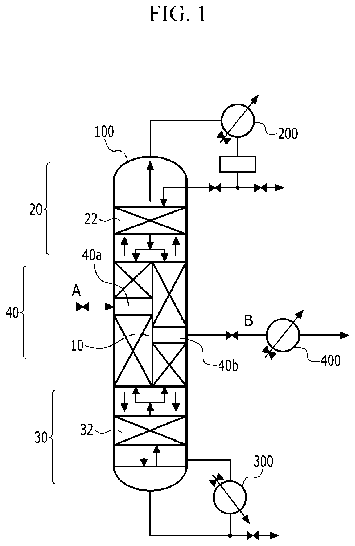
[0075]In order to purify high-purity toluene diisocyanate including inhibition of the dimerization reaction, the feed was applied to the reactive dividing wall column shown in FIG. 1. Here, the feed had a composition including 1800 ppm of low-boiling component, 7 wt % of high-boiling component, 200 ppm of toluene diisocyanate dimer, and 92.8 wt % of toluene diisocyanate. In addition, the theoretical stage of the reactive dividing wall column was set to 30 stages in total.
[0076]Example 1 was performed by reducing the pressure and temperature of the condenser, reducing the pressure drop in the reactive dividing wall column, and also reducing the retention time according to conditions shown in Table 1 below.
[0077]
TABLE 1Operating conditionUnitValueCondenser pressuretorr15Condenser temperature° C.54.5Reaction mixture retentionsec.46time in columnReboiler pressuretorr30Falling film evaporatorReboiler temperature° C.157.0Retention time in reboilersec.12Pressure drop in columntorr15Product qu
example 2
[0079]Example 2 was performed in the same manner as in Example 1 except that after toluene diisocyanate was separated and purified, when the purified toluene diisocyanate was quenched by using a side product quencher, a quenching temperature was 25° C.
[0080]
TABLE 2Operating conditionUnitValueCondenser pressuretorr15Condenser temperature° C.54.5Reaction mixture retentionsec.46time in columnReboiler pressuretorr30Falling film evaporatorReboiler temperature° C.157.0Retention time in reboilersec.12Pressure drop in columntorr15Product quencher° C.25Quenching temperatureDimer amount in productppm442High-boiling component amountwt %7
[0081]From results of Table 2, it could be appreciated that the dimer in the product could be reduced as compared to the conventional case by controlling the temperature to 40° C. or less during the quenching of the purified toluene diisocyanate.
reference example 1
[0082]Reference Example 1 was performed in the same manner as in Example 1 except that the retention time in the reboiler was changed as shown in Table 3.
[0083]
TABLE 3Operating conditionUnitValueCondenser pressuretorr15Condenser temperature° C.54.5Reaction mixture retentionsec.46time in columnReboiler pressuretorr30Falling film evaporatorReboiler temperature° C.157.0Retention time in reboilersec.300Pressure drop in columntorr15Product quencher° C.40Quenching temperatureDimer amount in productppm444High-boiling component amountwt %7.2
[0084]From results of Table 3, in Reference Example 1, the dimer amount in the product could be reduced as in Examples 1 and 2, but an amount of high-boiling component was increased.
PUM
 Abstract
Description
Claims
Application Information
 - R&D Engineer
- R&D Manager
- IP Professional
- Industry Leading Data Capabilities
- Powerful AI technology
- Patent DNA Extraction
Browse by: Latest US Patents, China's latest patents, Technical Efficacy Thesaurus, Application Domain, Technology Topic.
© 2024 PatSnap. All rights reserved.Legal|Privacy policy|Modern Slavery Act Transparency Statement|Sitemap