Injector driving control apparatus

Inactive Publication Date: 2002-12-19
HITACHI LTD
View PDF0 Cites 39 Cited by
  • Summary
  • Abstract
  • Description
  • Claims
  • Application Information

AI Technical Summary

Problems solved by technology

If the current value is set for a low fuel pressure, increases in the fuel pressure will prevent the valve from opening, or even if the valve opens, there will be a great delay in the opening of the valve.
Therefore, since the application of a voltage higher than the battery voltage will have been completed by the time the valve opens, it will not be possible for the open status of the valve to be maintained.
This problem relates to the duration of the current waveform.
Conversely, if the current value is set for a high fuel pressure, decreases in the fuel pressure will cause the valve to close too early.
Under such a situation, compared with the situation that the c

Method used


Image

  • Injector driving control apparatus
  • Injector driving control apparatus
  • Injector driving control apparatus

Examples


Embodiment Construction

[0016] One embodiment of the injector driving control apparatus according to the present invention is described in detail below using drawings.

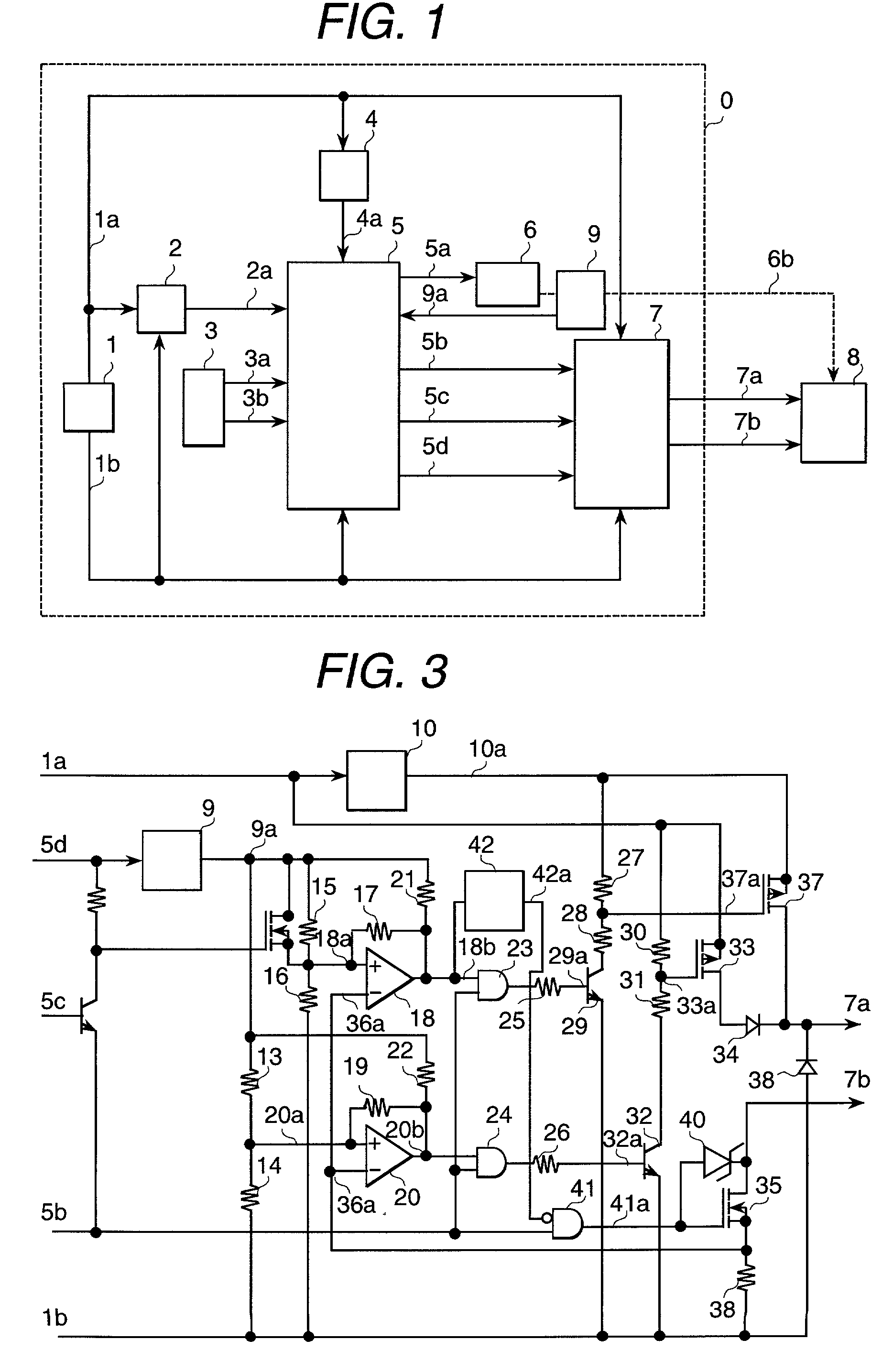
[0017] FIG. 1 is a block diagram for realizing the operation of the present invention.

[0018] Injector driving control apparatus 0 sends to a CPU 5 at least a reference position signal 3a, which indicates the piston position of an internal combustion engine that is detected by an internal combustion engine rotation detector 3, and an angle signal 3b, which indicates the rotational speed of the internal combustion engine. In CPU 5, a fuel pump 6 for supplying a fuel to the injector 8 is controlled by a fuel pump control signal 5a, and the pressure of the fuel to be supplied to injector 8 is detected by a fuel pressure sensor 9. The resulting signal is sent to CPU 5 as a fuel pressure signal 9a. Supply of power to injector driving control apparatus 0 is accomplished by supplying the voltage of a battery 1 as a battery power signal 1a, and after con


PUM


Abstract

Providing an injector driving control apparatus that operates with minimum power consumption while ensuring linearity (proportionality between the current supply duration and fuel injection volume of the injector) in a wide fuel pressure range. Providing a coil current feedback circuit and controlling the current feedback duration according to fuel pressure after applying the current at a boost voltage. The present invention enables optimal control of the injector and hence, the improvement of its fuel injection volume characteristics (linearity) and the reduction of the heat generated in the injector driving control circuits.

Description


Claims


Application Information

Patent Timeline
Owner HITACHI LTD
Why Eureka
Try Eureka