Socket connector

a socket connector and connector technology, applied in the direction of multi-conductor cable end pieces, fixed connections, coupling device connections, etc., can solve the problems of difficult to ensure the coplanarity of the soldering parts, and the problem may even be worse, and achieve good coplanarity performan

Inactive Publication Date: 2005-08-04
HON HAI PRECISION IND CO LTD
View PDF6 Cites 9 Cited by
  • Summary
  • Abstract
  • Description
  • Claims
  • Application Information

AI Technical Summary

Benefits of technology

The objective this new design solves by providing multiple contact pairs that have excellent solderability on both sides for better electrical connection between devices like connectors or other electronic components.

Problems solved by technology

This patented technical solution described by the inventor relates to improving the design of small electronics devices that use plug connections due to their compact size. While traditional methods have been developed over time, these new techniques require better alignment between certain parts within the device's circuit board or printed wiring boards during assembly. Therefore, there needs improvement in existing designs without compromising performance capabilities.

Method used


Image

  • Socket connector
  • Socket connector
  • Socket connector

Examples


Embodiment Construction

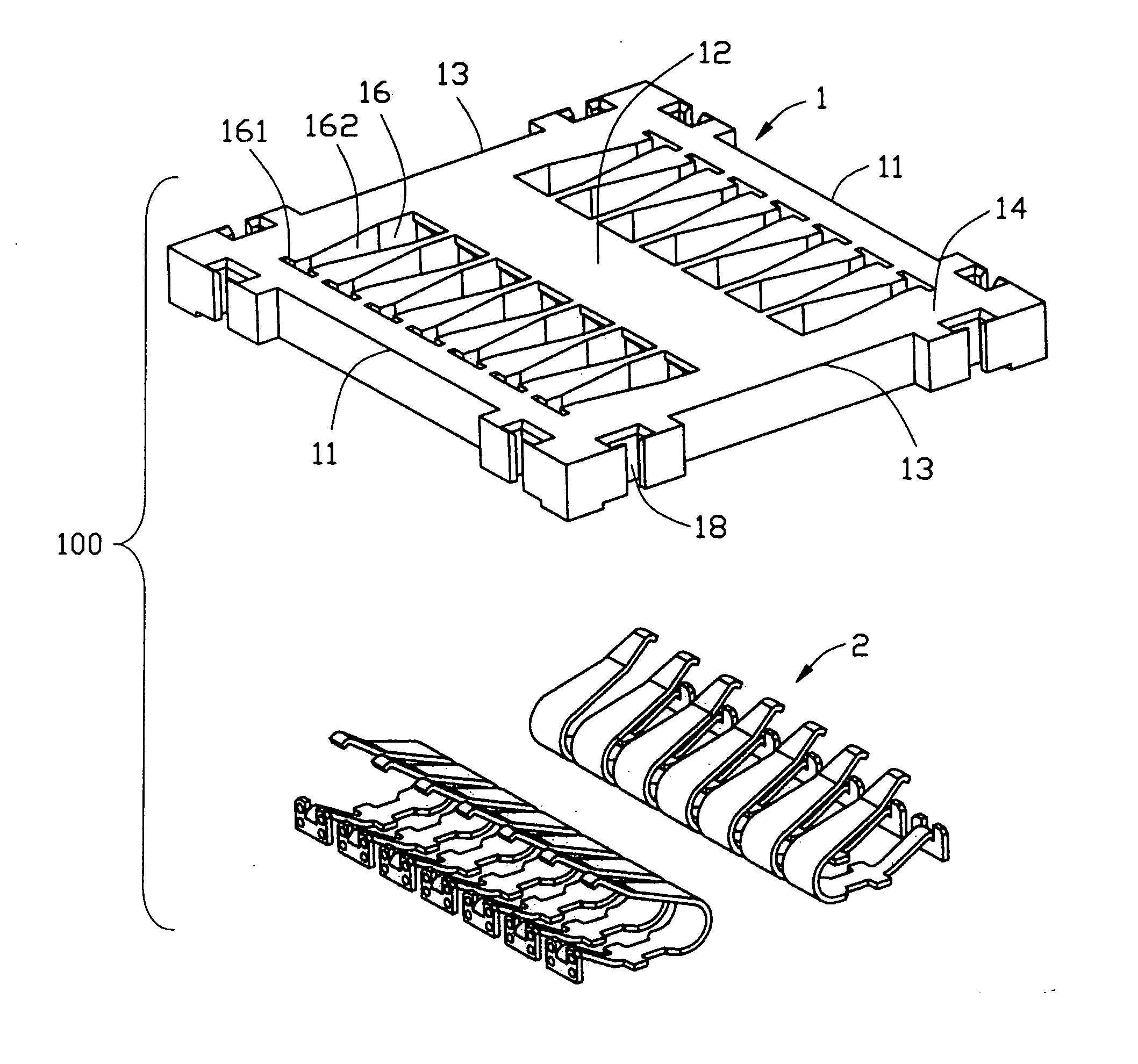
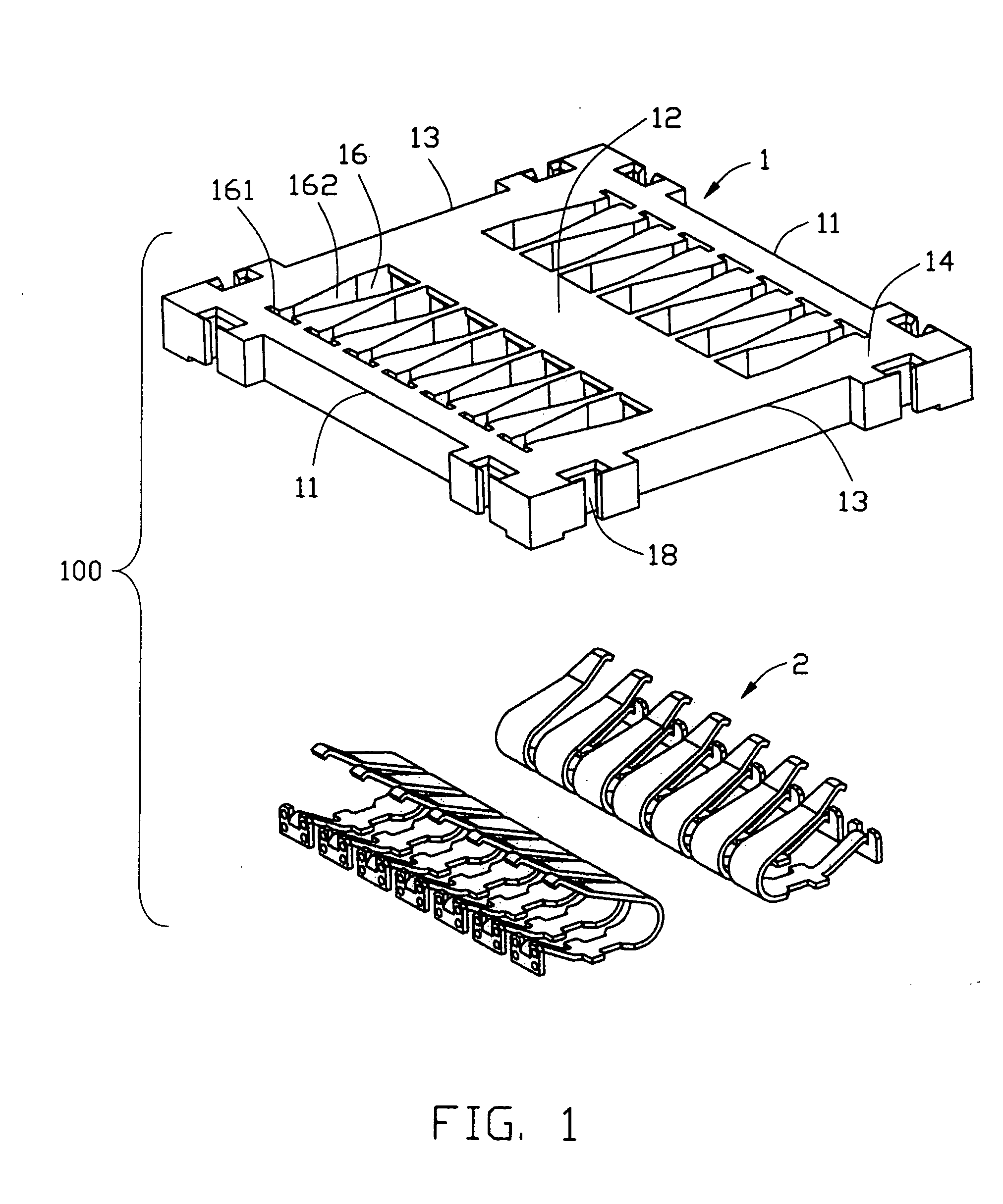
[0018] Referring to FIGS. 1 and 2, a socket connector 100 in accordance with the present invention comprises an insulative housing 1 and a plurality of contacts 2.

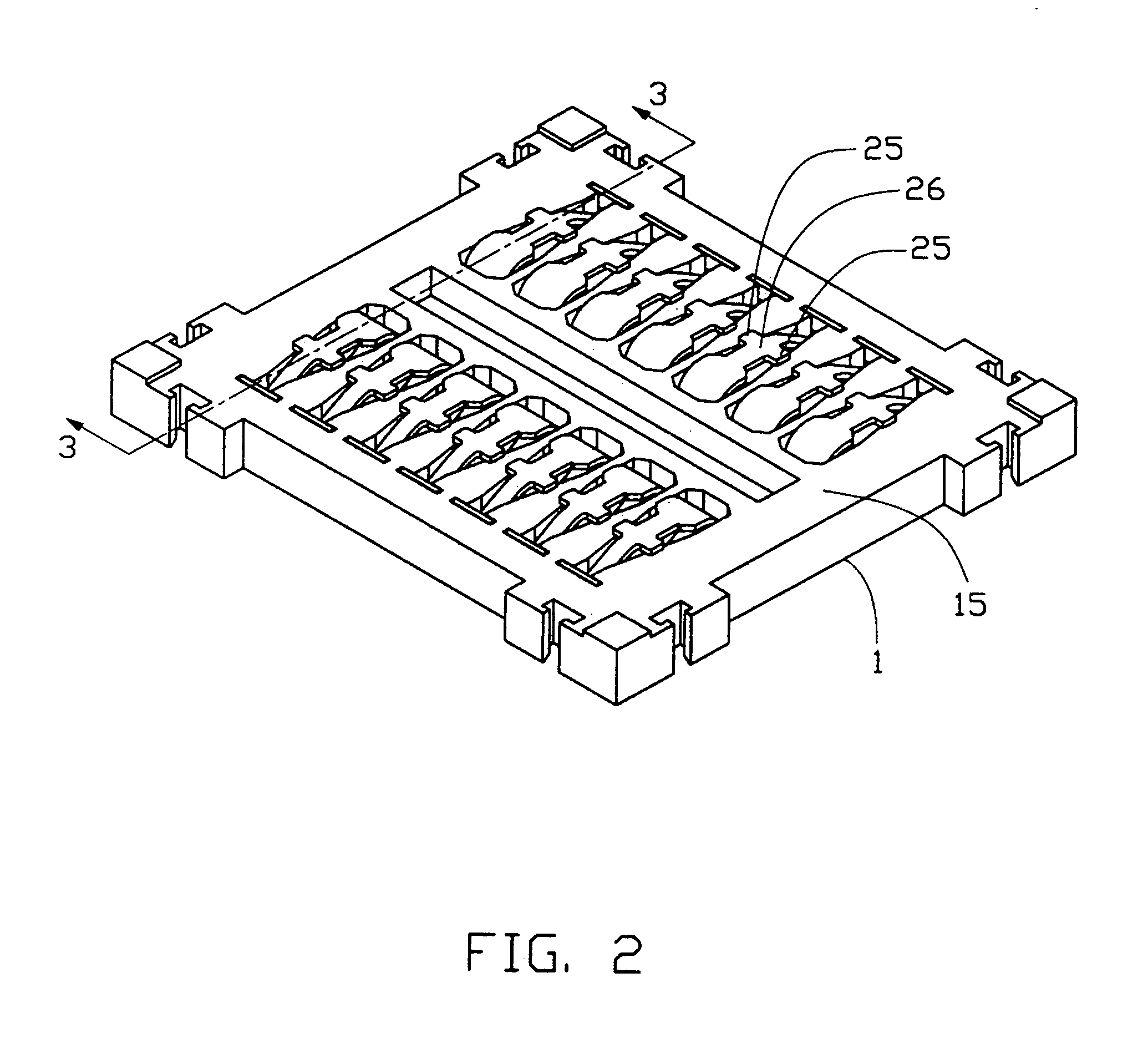
[0019] The insulative housing 1 comprises opposite side walls 11, opposite end walls 13 respectively perpendicular to the side walls 11 and a central wall 12 parallel to the side walls 11 and connecting with central portions of the end walls 13. The insulative housing 1 is symmetrical with the central wall 12. The insulative housing 1 has a top surface 14 and a bottom surface 15. A plurality of passageways 16 is defined through the top surface 14 and the bottom surface 15 in the insulative housing 1. The passageways 16 are arranged in two rows and are symmetrical with the central wall 12. Each passageway 16 has a slit 161 located adjacent to a corresponding side wall 11, and a receiving groove 162 extending in a direction perpendicular to the slit 161 and towards the central wall 12. The insulative housing 1 has a plurality


PUM


Abstract

A socket connector (100) includes an insulative housing (1) and a number of contacts (8). The insulative housing has a bottom surface (15), and defines a number of passageways (16) extending through a bottom surface thereof. The contacts are respectively received in the number of passageways. Each contact is formed with a holding portion (22) engaging with the insulative housing. A soldering portion (26) extends from the holding portion. A contacting portion (29) extends from the soldering portion. The soldering portion has a pair of positioning portion (25) laterally extending from side edges thereof and abutting against the bottom surface.

Description


Claims


Application Information

Patent Timeline
Owner HON HAI PRECISION IND CO LTD
Why Eureka
Try Eureka