System, method, and computer program product for magneto-optic device display

a technology of magneto-optic devices and display devices, applied in the field of waveguides, can solve the problems of affecting the properties of radiation other than polarization angle, requiring considerable magnetic control fields, and relatively high cost per picture element (pixel), so as to enhance the short-length property influencing characteristics of the influencer, enhance the responsiveness of the radiation-influencing property, and enhance the effect of short-length property influencing characteristics

Inactive Publication Date: 2005-09-15
ST SYNERGY
View PDF19 Cites 136 Cited by
  • Summary
  • Abstract
  • Description
  • Claims
  • Application Information

AI Technical Summary

Benefits of technology

This patented device has several technical benefits: it allows for improved properties such as enhanced absorption efficiency without adding extra materials like glass fibers, which can affect their performance significantly more than traditional ways they were designed previously. It also reduces costs compared to existing techniques used during fabrication. Additionally, these devices have been developed through different approaches based on specific needs and capabilities.

Problems solved by technology

Technologies described involve improving the performance of ferroelectric/ferrogen compounds called ceribbles in optoelectrical mirror reflectors. These compositions exhibiting excellent properties like low loss, fast response times, stable operation under extreme conditions, etceterioratino effects, reduced complexity, increased efficiency, improved precision control during assembly, and more reliable manufactures. They offer several technical benefits including enhanced sensitivity, lower power consumption compared to existing techniques, reduction of waste products, and better overall quality control.

Method used


Image

  • System, method, and computer program product for magneto-optic device display
  • System, method, and computer program product for magneto-optic device display
  • System, method, and computer program product for magneto-optic device display

Examples


second embodiment

[0219]FIG. 12 is a schematic diagram of a second specific implementation of the system shown in FIG. 38 including a partially conductively coated preform without a superficial helical cut. This second example is an alternative to the coated preform which is cut with a helical track as shown in FIG. 11, This second embodiment includes a partially coated preform 1200 that is twisted (shown by arrow 1205) and precessed in the direction of the Y-axis without a facilitating helical cut. A tool removes some of the coating to leave a helical conductive strip that wraps around the waveguiding structure. Preform 1200 is then drawn to produce a waveguiding structure 1210 and twisted using a first yoke 1215 and a second yoke 1220 while the material is above its vitreous temperature, such that the twist persists after cooling without need for a confining jacket material. In the preferred embodiment, the yokes are oppositely twisting structures to improve the number of twists per unit length. The r

third embodiment

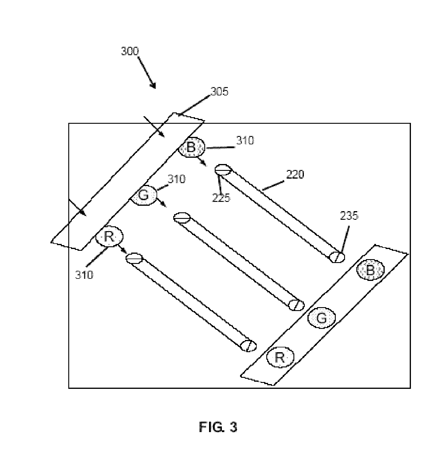
[0222]FIG. 13 is a schematic diagram of a third specific implementation of the system shown in FIG. 38 including a conductive element 1300 embedded / applied into / onto a preform 1305. This third embodiment provides for conductive element (e.g., a wire, conductive polymer and the like) 1300 to be embedded in or disposed within a preform 1305 as the preform rotates and precesses along the Y-axis (which as depicted in FIG. 52 is downward in the drawing tower) to produce a longitudinally extending pre-coilform structure 1310. Conductive element 1300 is fed into or laid upon or otherwise disposed in connection with preform 1305. Rotation of preform 1305 (and any necessary precession along the Y-axis) containing conductive element 1310 produces the initial helical structure within preform 1305 prior to drawing. Preform 1305 is then drawn to produce a waveguiding structure 1315 and twisted using a first yoke 1320 and a second yoke 1325 while the material is above its vitreous temperature, s


PUM


Abstract

An apparatus and method for a radiation switching array, including a first radiation wave modulator and a second radiation wave modulator proximate the first modulator, each the modulator having a transport for receiving a wave component, the transport including a waveguide having a guiding region and one or more bounding regions; and a plurality of constituents disposed in the waveguide for enhancing an influencer response in the waveguide; and an influencer, operatively coupled to the transport and responsive to a control signal, for affecting a radiation-amplitude-controlling property of the wave component by inducing the influencer response in the waveguide as the wave component travels through the transport; and a controller, coupled to the modulators, for selectively asserting each the control signal to independently control the amplitude-controlling property of each the modulator. A switching method including (a) receiving a wave component at each of a plurality of transports proximate each other, each transport including a waveguide having a guiding region and one or more bounding regions with a plurality of constituents disposed in the waveguide for enhancing an influencer response in the waveguide; and (b) affecting independently a radiation-amplitude-controlling property of each the wave component as it travels through each the waveguide.

Description


Claims


Application Information

Patent Timeline
Owner ST SYNERGY
Why Eureka
Try Eureka