Demultiplexer circuit

a multi-channel circuit and multi-channel technology, applied in the direction of code conversion, data switching network, synchronisation signal speed/phase control, etc., can solve the problems of increasing power consumption, reducing data transfer rate, and not considering the bit deviation of the comma code in the received serial data. achieve the effect of improving the data transfer ra

Inactive Publication Date: 2005-10-06
RENESAS ELECTRONICS CORP
View PDF1 Cites 16 Cited by
  • Summary
  • Abstract
  • Description
  • Claims
  • Application Information

AI Technical Summary

Benefits of technology

The technical effect of this patented invention is that it allows for faster data transmission rates while maintaining the same duty cycle (the ratio between active time and standby) on the circuit's frequencies. This means that even if there are slight variations or errors in the commands being sent over the network, they won't affect the overall performance of the system.

Problems solved by technology

The technical problem addressed by this patent is how to efficiently convert digital signals between different types of formats without sacrificing accuracy during transmission over long distances.

Method used


Image

  • Demultiplexer circuit
  • Demultiplexer circuit
  • Demultiplexer circuit

Examples


Embodiment Construction

[0032] Referring to the drawings, preferred embodiments of the present invention are explained in detail.

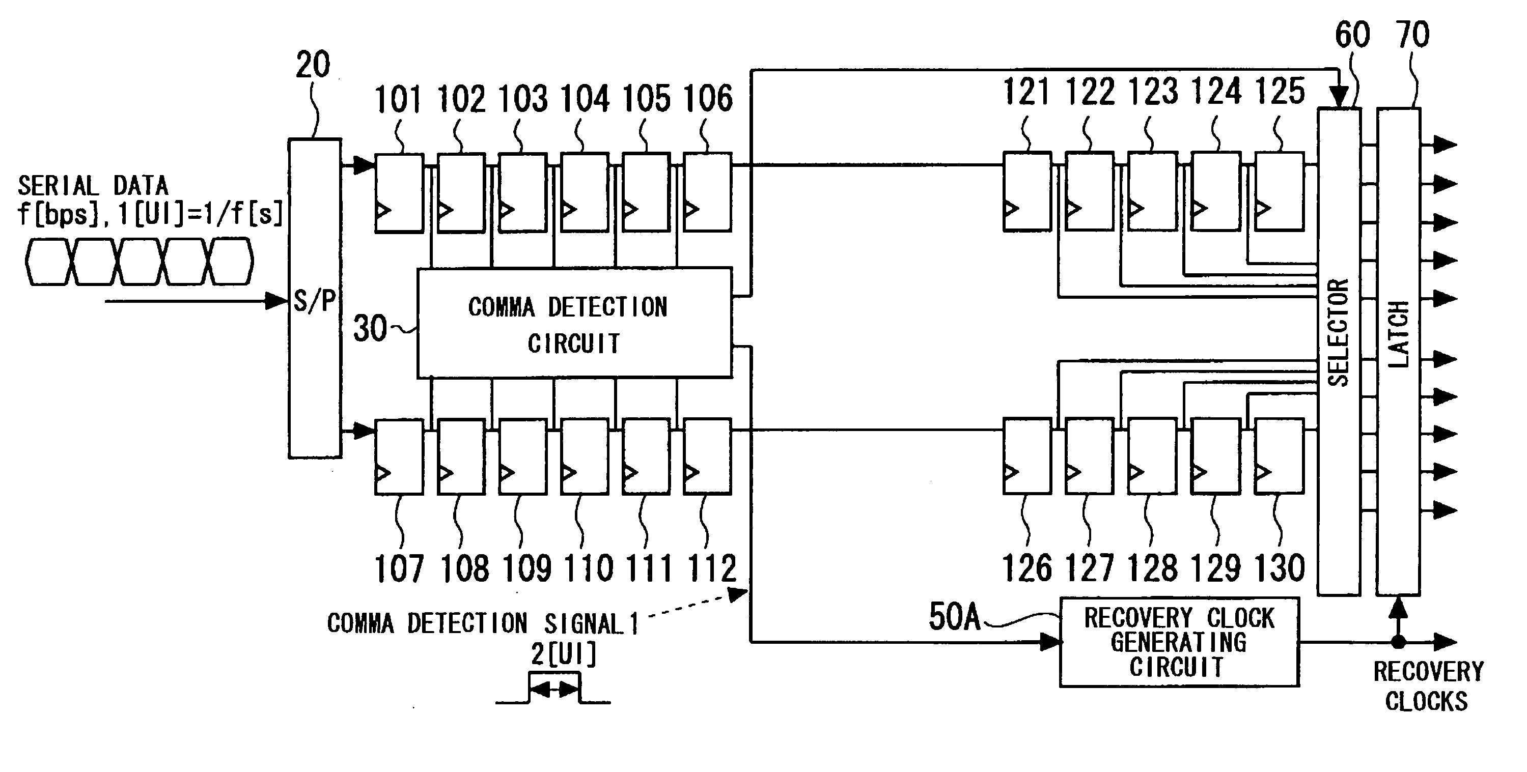
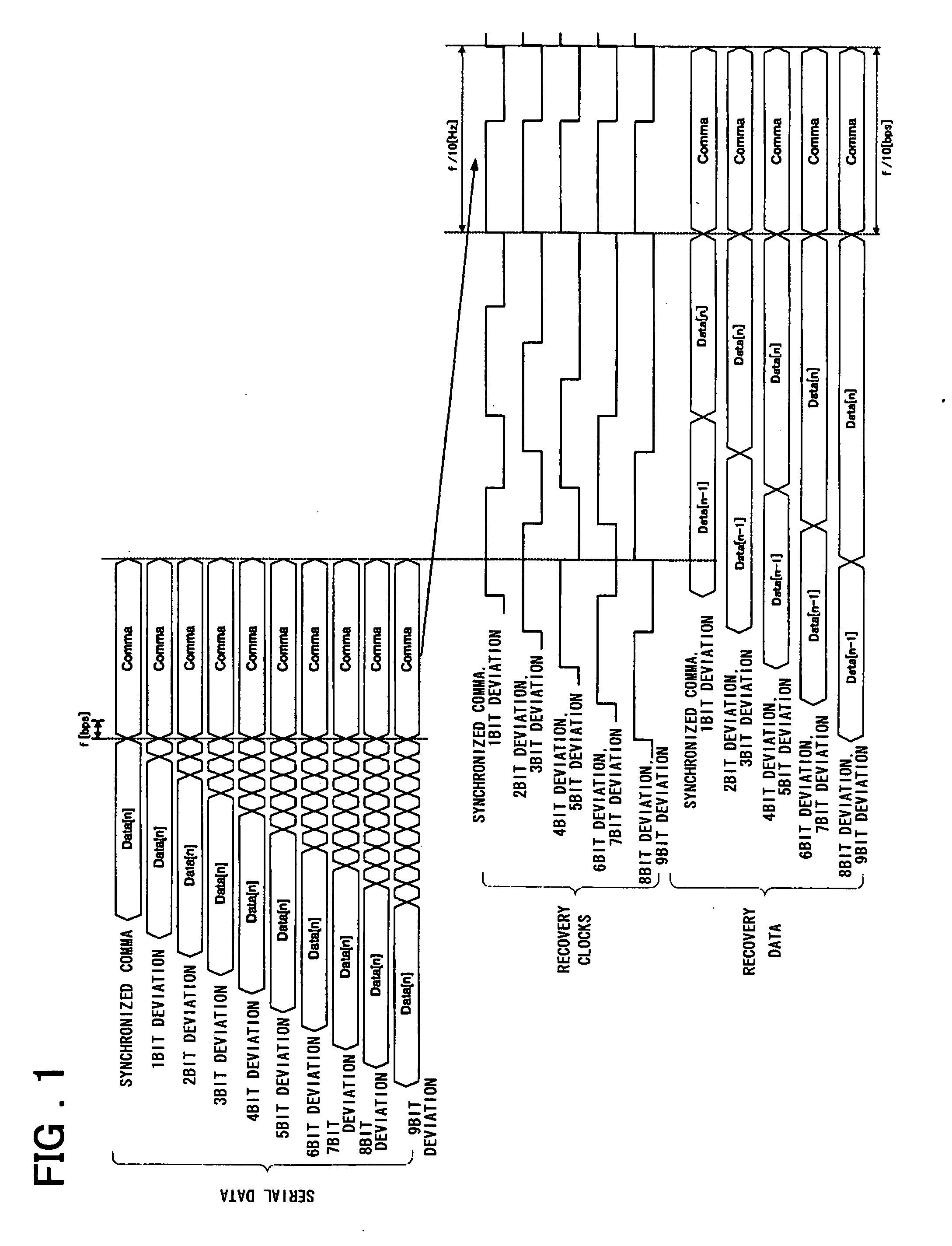
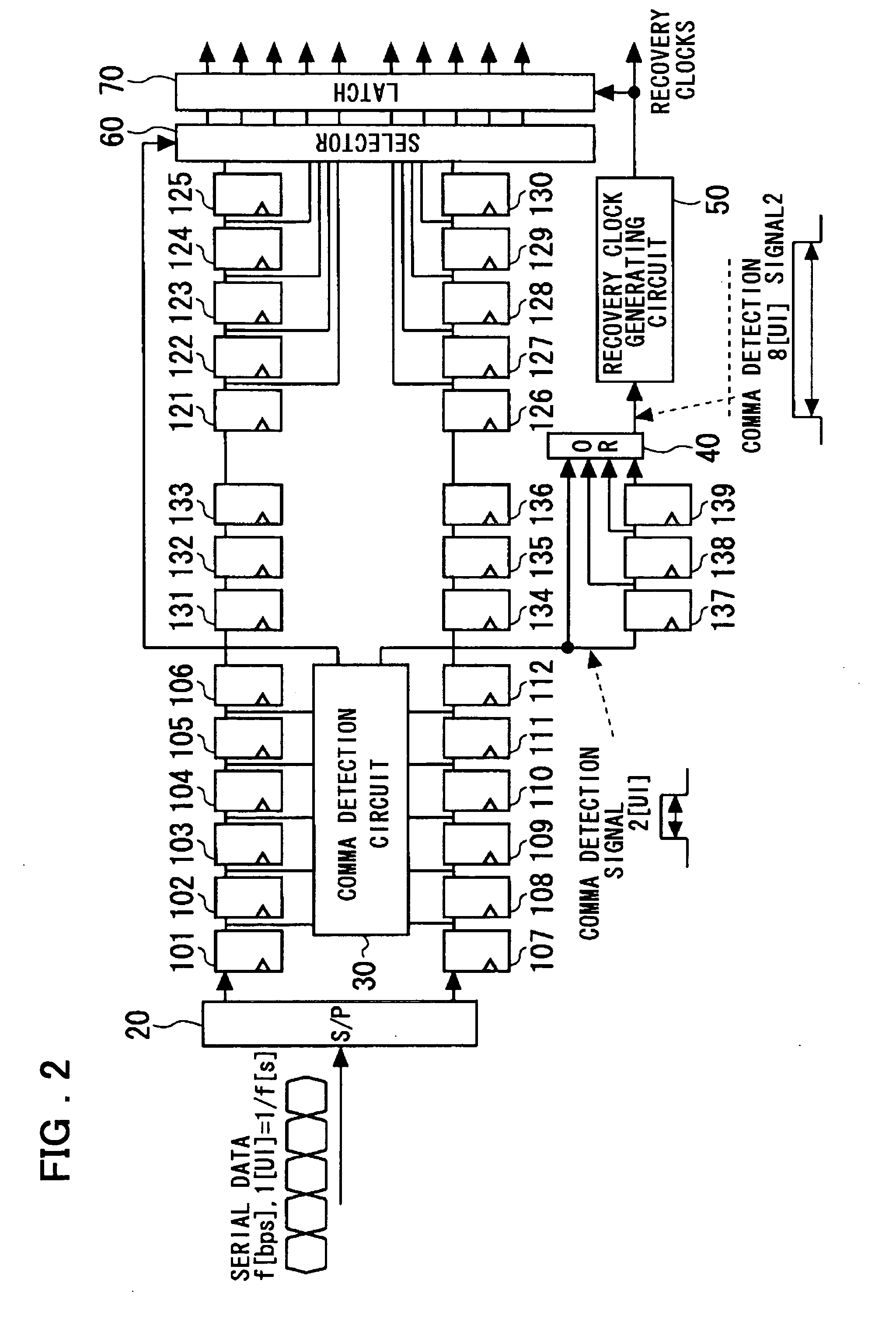
[0033]FIG. 1 illustrates the operating principle of an embodiment of the present invention. Specifically, FIG. 1 illustrates the timing operation of a demultiplexer (macro-cell) at a high-speed serial interface adapted for effecting 1:10 serial-to-parallel conversion and byte alignment. Referring to FIG. 1, recovery data of f / 10 bps ( . . . , Data[n−1], Data[n], Comma) and recovery clocks of f / 10 Hz are generated against serial data input with a transfer rate of f bps. It is noted that the received serial data is 8 B-10 B converted data. The received serial data is processed with byte alignment every symbol (every ten bits), responsive to rising edges of the recovery clocks, to issue 10-bit output parallel data. Moreover, when the 10-bit command code (Comma), made up by preset logical bits, as mentioned previously, is detected, the period of the recovery clocks is adjusted. In


PUM


Abstract

Demultiplexer capable of coping with bit deviation of a comma code to suppress increase of operating frequency. The demultiplexer comprises a circuit (20) serially supplied with received data to perform serial-to-parallel conversion on the received data, a comma detection circuit (30) for activating a comma detection signal on detection of coincidence between the serial data transferred on parallel paths with clocks corresponding to received clocks halved in frequency and a comma code, and a control circuit (137-139, 40) for elongating and outputting the activated time duration of the comma detection signal by a predetermined time. The demultiplexer also includes a recovery clock generating circuit (50) composed of a state machine transferred between different states based on the frequency-halved clocks and which, on receipt of an output signal of a control circuit (40), varies the period of the recovery clock to output the resulting clock. The demultiplexer also includes first and second delay circuits (131-133, 134-136) and first and second shift registers (121-125, 126-130) for receiving outputs of the first and second delay circuits to convert outputs into parallel data. The demultiplexer also includes a latch circuit (70) receiving outputs of respective stages of the first and second shift registers in parallel and sampling parallel outputs with recovery clocks to output resulting parallel data. In case of occurrence of bit deviation, recovery clocks are elongated by a predetermined time duration for only one period depending on the state of bit deviation.

Description


Claims


Application Information

Patent Timeline
Owner RENESAS ELECTRONICS CORP
Why Eureka
Try Eureka