Method and Apparatus for Controlling Part Movement

Inactive Publication Date: 2005-10-27
FIRST RESPONSE TECHN SERVICES
View PDF5 Cites 9 Cited by
  • Summary
  • Abstract
  • Description
  • Claims
  • Application Information

AI Technical Summary

Benefits of technology

[0010] This disclosure describes an apparatus and a method for securing, moving and positioning a workpiece in a variety of ways within a machine so that work can be performed upon the workpiece. Briefly described in architecture, the apparatus has an electrical actuator, a shaft having a ball screw groove and a ball spline groove, a motor, a ball screw nut fitted about the shaft, a ball spline and a ball spline nut fitted about the shaft and an independent bearing fitted to the top of the shaft. A servo-motor is connected to the ball screw and a second servo-motor is connected to the ball spline. A programmable controller or computer is

Problems solved by technology

This type of scanning is reasonably precise, but is limited in its weight capacity due to the use of the cantilever mechanism and the forces applied to the lifting mechanism.
The current methods have some limitations to them.
By this, we mean that the method for scan induction hardening does not provide for a means to lift and index.
Similarly, the means for lifting and indexing does not provide for a continuous scan of a workpiece.
Neither of these induction hardening processes provide for a means to do “Pop Up” induction hardening.
Secondly, the existing methods utilize a table or “L” shaped cantilever for positioning the workpiece.
This s

Method used


Image

  • Method and Apparatus for Controlling Part Movement
  • Method and Apparatus for Controlling Part Movement
  • Method and Apparatus for Controlling Part Movement

Examples


Embodiment Construction

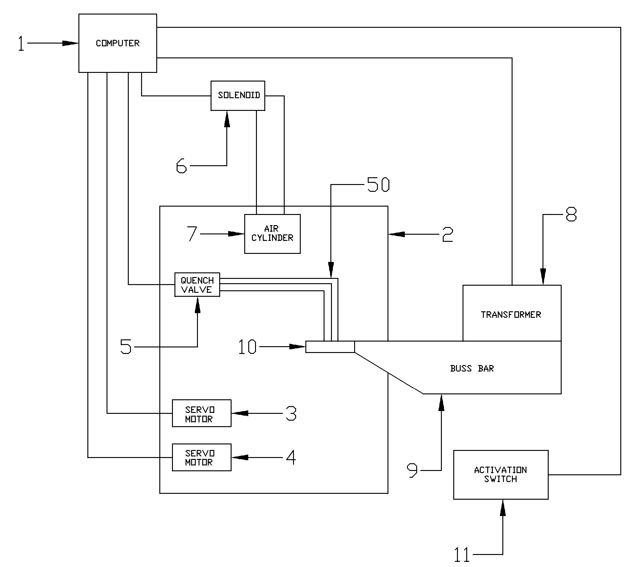
[0019] To facilitate the description of the invention, it is useful to define some terminology solely for this purpose. The terminology should not be construed as limiting the generality of the invention. For the purpose of this description: [0020] 1. Computer represents any type of computer, programmable controller or manual input used in providing directions for any of the components connect to the computer; [0021] 2. Software represents the programming code or applets utilized by the computer; [0022] 3. The electrical connection topology of the computer and the other components is not limited to hardwiring and may include wireless communication.

[0023] The present invention consists of an apparatus and a method for the control and movement of a workpiece, and the actuation of a tool, such that the apparatus can provide the workpiece with linear motion, rotational motion, lift and hold motion, drop and index motion or any combination of these motions. Although the invention is descri


PUM

PropertyMeasurementUnit
Angleaaaaaaaaaa

Abstract

There is disclosed herein an apparatus and a method in which a workpiece is loaded into the apparatus and the apparatus then moves and positions the workpiece in a multitude of directions based upon the directions and controls supplied to the apparatus through either a computer and applets, a programmable controller and/or through manual intervention. The apparatus can move the workpiece linearly to a predetermined position, rotate the workpiece in a continuous motion, index the workpiece incrementally and/or do any combination of those movements. The apparatus can also control other components such as turning coolant and/or quench valves on and off as desired or powering working tools such as an induction hardening coil. The workpiece is loaded directly on the center of the apparatus movement and positioning device for increased capacity loading and precision movement.

Description


Claims


Application Information

Patent Timeline
Owner FIRST RESPONSE TECHN SERVICES
Why Eureka
Try Eureka