Method for detecting a mass density image of an object

a mass density image and object technology, applied in material analysis using wave/particle radiation, instruments, nuclear engineering, etc., can solve the problems of limited acceptance of dei by radiologists and loss of good absorption-based radiographs, and achieve better signal-to-noise ratios, reduce x-ray doses, and reduce radiation doses

Active Publication Date: 2005-11-24
ILLINOIS INSTITUTE OF TECHNOLOGY
View PDF5 Cites 0 Cited by
  • Summary
  • Abstract
  • Description
  • Claims
  • Application Information

AI Technical Summary

Benefits of technology

This patent describes a way to make it easier to see small objects without being affected by their own weight or shape. It uses algorithms to reduce unwanted light from X rays striking them while still capturing important details about its properties like mass density. By reducing these unwanted distortions, the resulting image will have improved quality and reduced radiation exposure.

Problems solved by technology

The technical problem addressed in this patent is how to produce an improved version of X-ray radiation called DEXRI, which allows for clearer detection of objects like tumors while reducing their impact on healthy tissue.

Method used


Image

  • Method for detecting a mass density image of an object
  • Method for detecting a mass density image of an object
  • Method for detecting a mass density image of an object

Examples


Embodiment Construction

[0025] One method of this invention provides a mass density image of an object. The mass density image shows contrast features of an object, similar to conventional radiography, without relying on the absorption of x-rays by the object. The mass density image of an object is obtained through an image processing algorithm used on images based on refraction characteristics of the object, such as refraction images obtained by Diffraction Enhanced Imaging (DEI). The mass density image of this invention can be obtained through DEI such as, for example, the x-ray imaging method disclosed in U.S. Pat. No. 5,987,095 issued to Chapman et al. and / or in U.S. Pat. No. 6,577,708 issued to Chapman et al., the entire disclosures of which are incorporated into this specification by reference.

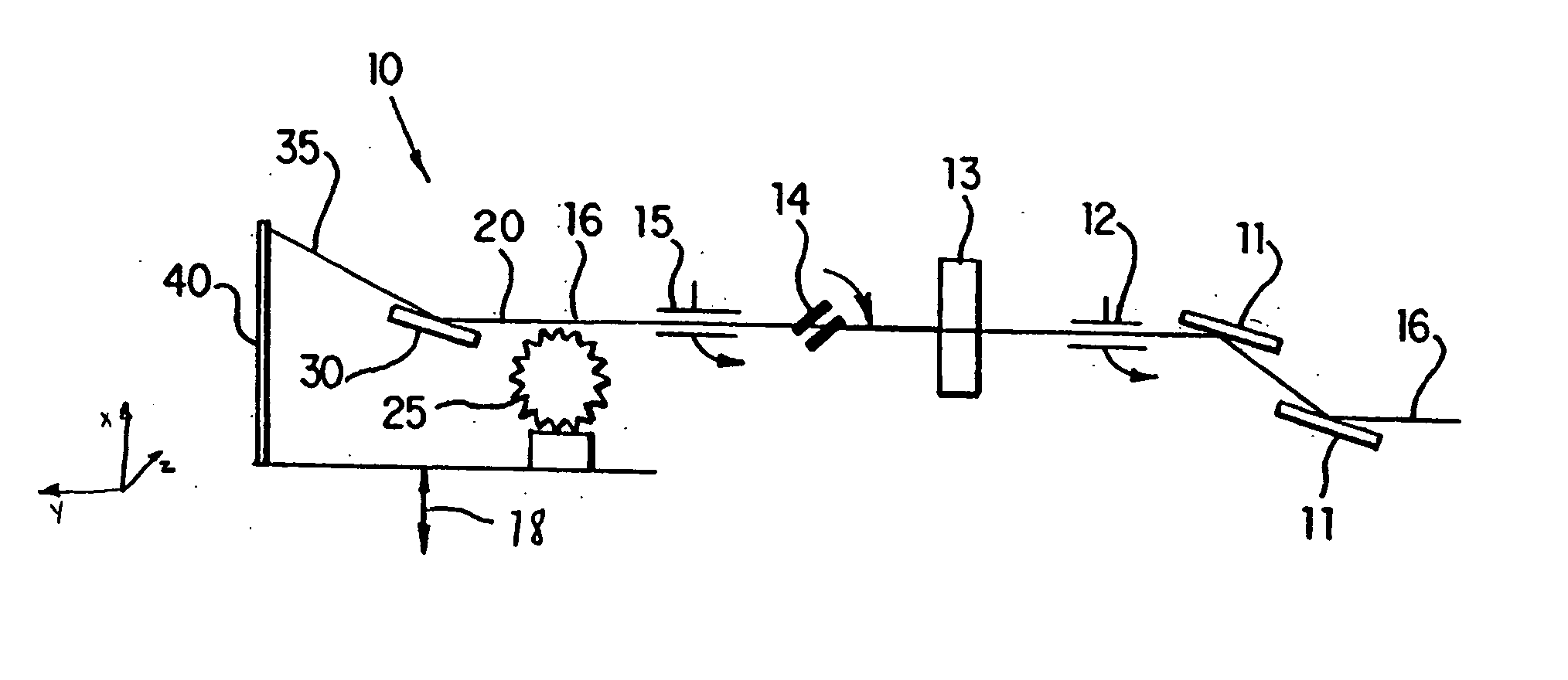
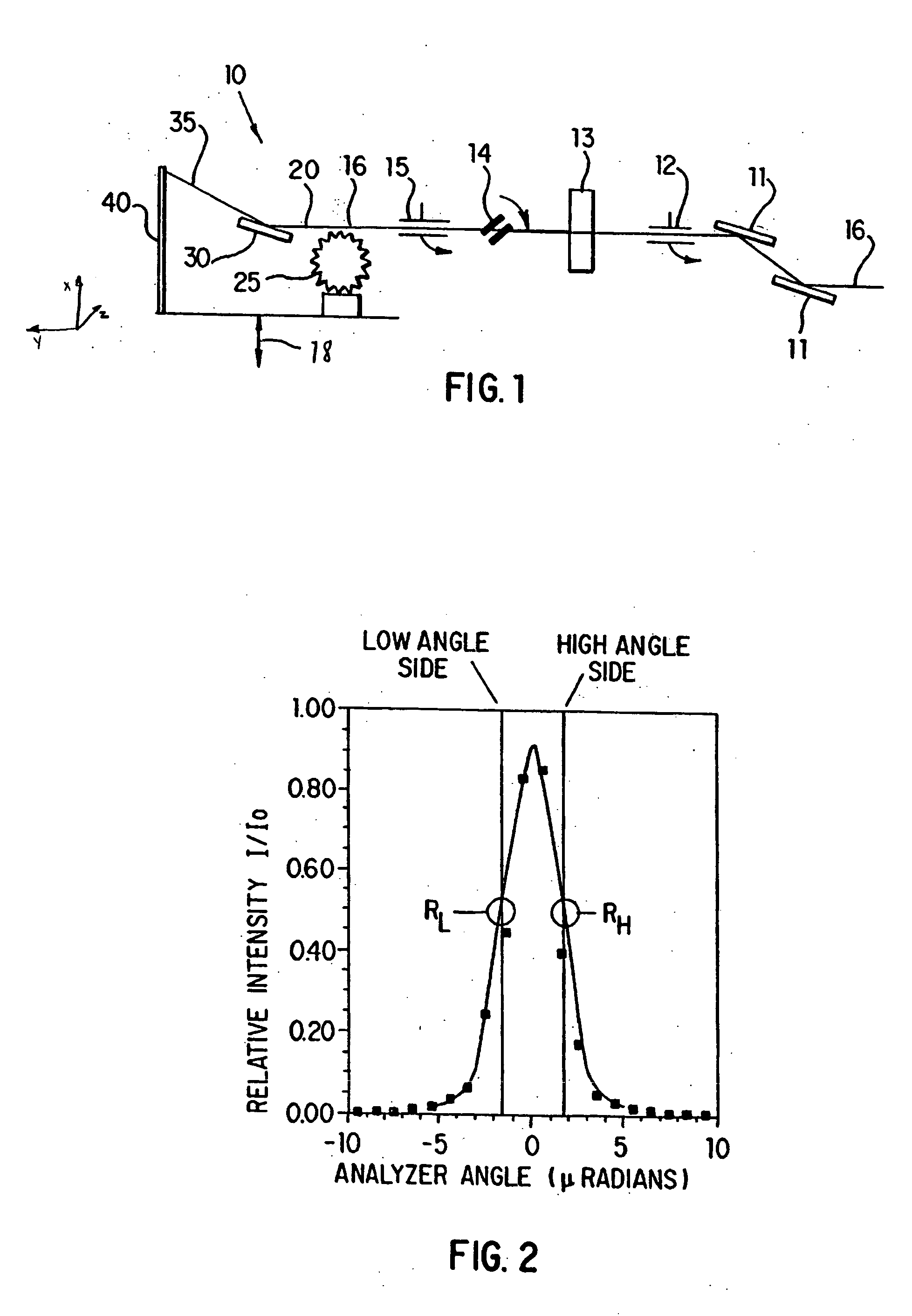
[0026]FIG. 1 shows a schematic diagram of an analyzer system 10, according to one preferred embodiment of this invention. FIG. 1 is similar to the crystal analyzer system shown in FIG. 1 of U.S. Pat. No. 5,987,


PUM


Abstract

A method for detecting a mass density image of an object. An x-ray beam is transmitted through the object and a transmitted beam is emitted from the object. The transmitted beam is directed at an angle of incidence upon a crystal analyzer. A diffracted beam is emitted from the crystal analyzer onto a detector and digitized. A first image of the object is detected from the diffracted beam emitted from the crystal analyzer when positioned at a first angular position. A second image of the object is detected from the diffracted beam emitted from the crystal analyzer when positioned at a second angular position. The first image and the second image are combined mathematically to derive a mass density image of the object.

Description


Claims


Application Information

Patent Timeline
Owner ILLINOIS INSTITUTE OF TECHNOLOGY
Why Eureka
Try Eureka