Countertop thermoelectric assembly

a thermoelectric assembly and counter top technology, applied in the field of counter top thermoelectric assembly, can solve the problems of high temperature, high cost and space of commercial refrigeration systems used in commercial kitchens, and food preparation surfaces that are typically not as naturally cool as desired

Inactive Publication Date: 2006-01-12
RUCKSTUHL KEITH
View PDF25 Cites 129 Cited by
  • Summary
  • Abstract
  • Description
  • Claims
  • Application Information

AI Technical Summary

Benefits of technology

This patent describes a system for adjusting the temperature on a cooked meal surface during processing. It includes two parts: a counter top that forms part of the surface and a thermoelectric unit placed under it. An electric control unit can be used to switch the thermoelectric unit from cooling or warming mode to cooling or warm up the surface. Another component called a thermocouple is also included. There are also sensors like temperature and humidity to monitor the condition of the meal being processed. Overall, this technology allows for precise temperature control over the meal's surface while maintaining consistent quality standards.

Problems solved by technology

The technical problem addressed by this patent is how to improve the cooling and heating capabilities of household chefs' workspace while minimizing costs and space requirements.

Method used


Image

  • Countertop thermoelectric assembly
  • Countertop thermoelectric assembly
  • Countertop thermoelectric assembly

Examples


Embodiment Construction

[0021] It will be apparent to those skilled in the art, that is, to those who have knowledge or experience in this area of technology, that many uses and design variations are possible for the improved countertop thermoelectric assemblies disclosed herein. The following detailed discussion of various alternative and preferred embodiments will illustrate the general principles of the invention with reference to countertop thermoelectric assemblies for use in cooling and / or heating residential or home food preparation surfaces such as kitchen countertops. Other embodiments suitable for other applications such as, for example, commercial food preparation surfaces or the like will be apparent to those skilled in the art given the benefit of this disclosure.

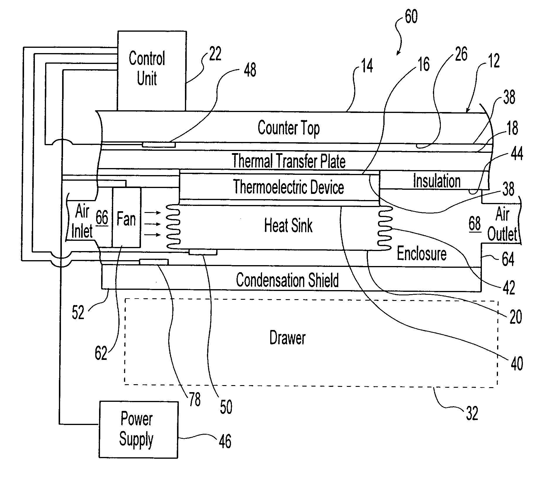
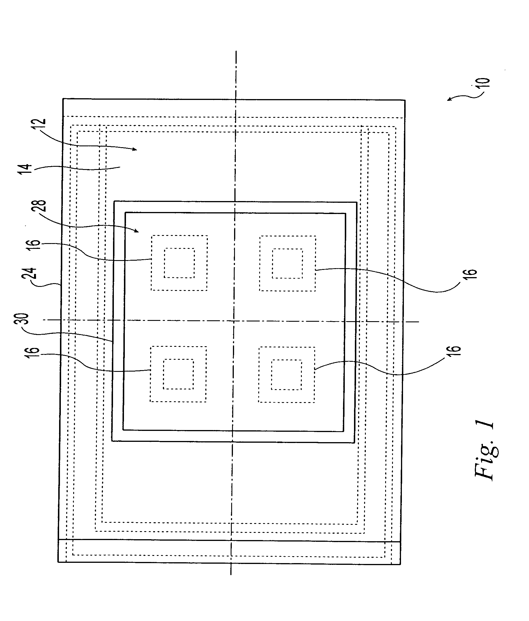
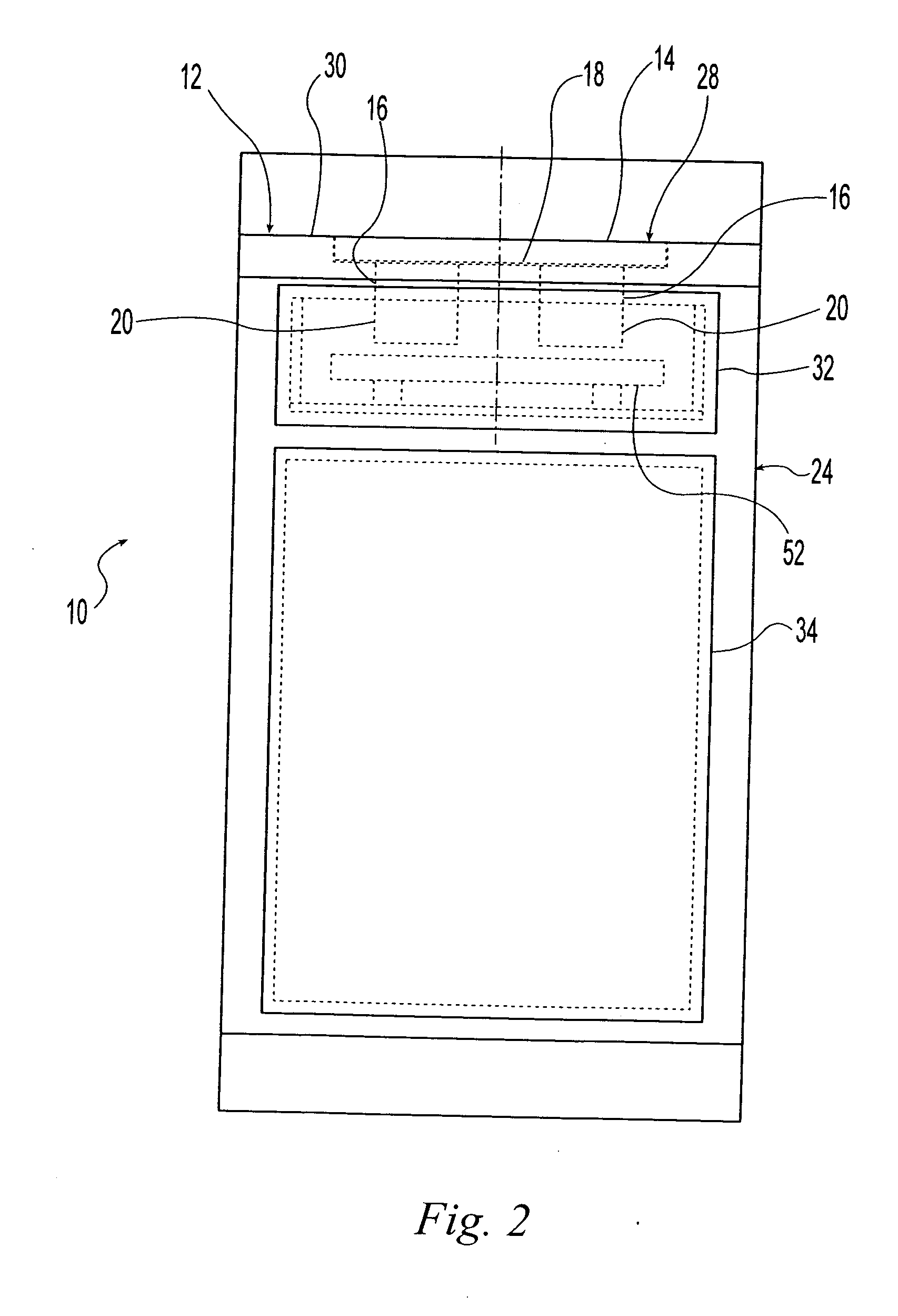
[0022] Referring now to the drawings, FIGS. 1 to 4 show a countertop thermoelectric assembly 10 installed on a residential kitchen countertop according to the present invention. The thermoelectric assembly 10 includes a panel such as


PUM


Abstract

A countertop thermoelectric assembly includes a countertop forming a food preparation surface at an upper side thereof, at least one Peltier effect device located below the countertop, a thermal transfer plate located between the countertop and the thermoelectric device, a heat sink in thermal communication with the thermoelectric unit, and a controller to selectively operate the thermoelectric unit to cool and/or warm the food preparation surface formed by the countertop. A first temperature sensor located to provide signals representative of a temperature of the countertop. A second temperature sensor located to provide signals representative of a temperature of the heat sink. A condensation shield is located below the heat sink. A moisture sensor is located to provide signals representative of moisture at the condensation shield. At least one fan is located below the countertop to direct air over the heat sink and/or the condensation shield.

Description


Claims


Application Information

Patent Timeline
Owner RUCKSTUHL KEITH
Why Eureka
Try Eureka