Scalable video encoding

a video encoding and scalable technology, applied in the field of video encoding, can solve the problems of reduced compression efficiency, increased coding overhead, and low quality of full picture, and achieve the effect of efficient scalability of the encoded video stream, significant reduction of drift effects, and reduction of the impact of basing motion compensation on a reduced data s

Inactive Publication Date: 2006-01-12
KONINKLIJKE PHILIPS ELECTRONICS NV
View PDF8 Cites 15 Cited by
  • Summary
  • Abstract
  • Description
  • Claims
  • Application Information

AI Technical Summary

Benefits of technology

In this patented technology, there exist two modes: 1) Transmission mode where image sequences are sent separately but combined together before transmission; 2) Compression mode that compresses images without affects their overall effectiveness due to lesser amount of bits needed compared to traditional methods like encoding videos alone. These techniques allow for better resolution and faster playback time by reducing interference between neighboring pixels while maintaining good picture quality.

Problems solved by technology

Technological Problem addressed in this patents relates to improving efficient transmission/reception of videos over wireless communication networks while also reducing their impact upon error rate caused by burst errors due to changes in network bandwidth usage during playback. Current methods involve either scaling down each resolution based on its own strength capability or adding extra layers if necessary. These techniques result in complicated hardware configurations and consume considerable computing resources. There exists a new method called Multiplex Scale Coding (MSC), described below, aiming towards achieving both lower costs and enhanced flexibility without sacrificially compromising any benefits provided by these technologies.

Method used


Image

  • Scalable video encoding
  • Scalable video encoding
  • Scalable video encoding

Examples


Embodiment Construction

[0029] A preferred embodiment of the invention will in the following be described with specific reference to the MPEG-2 video compression scheme, but it will be apparent that the invention is not limited to this application and applies equally to many other video encoding schemes including non-compressed video encoding schemes and transcoding schemes.

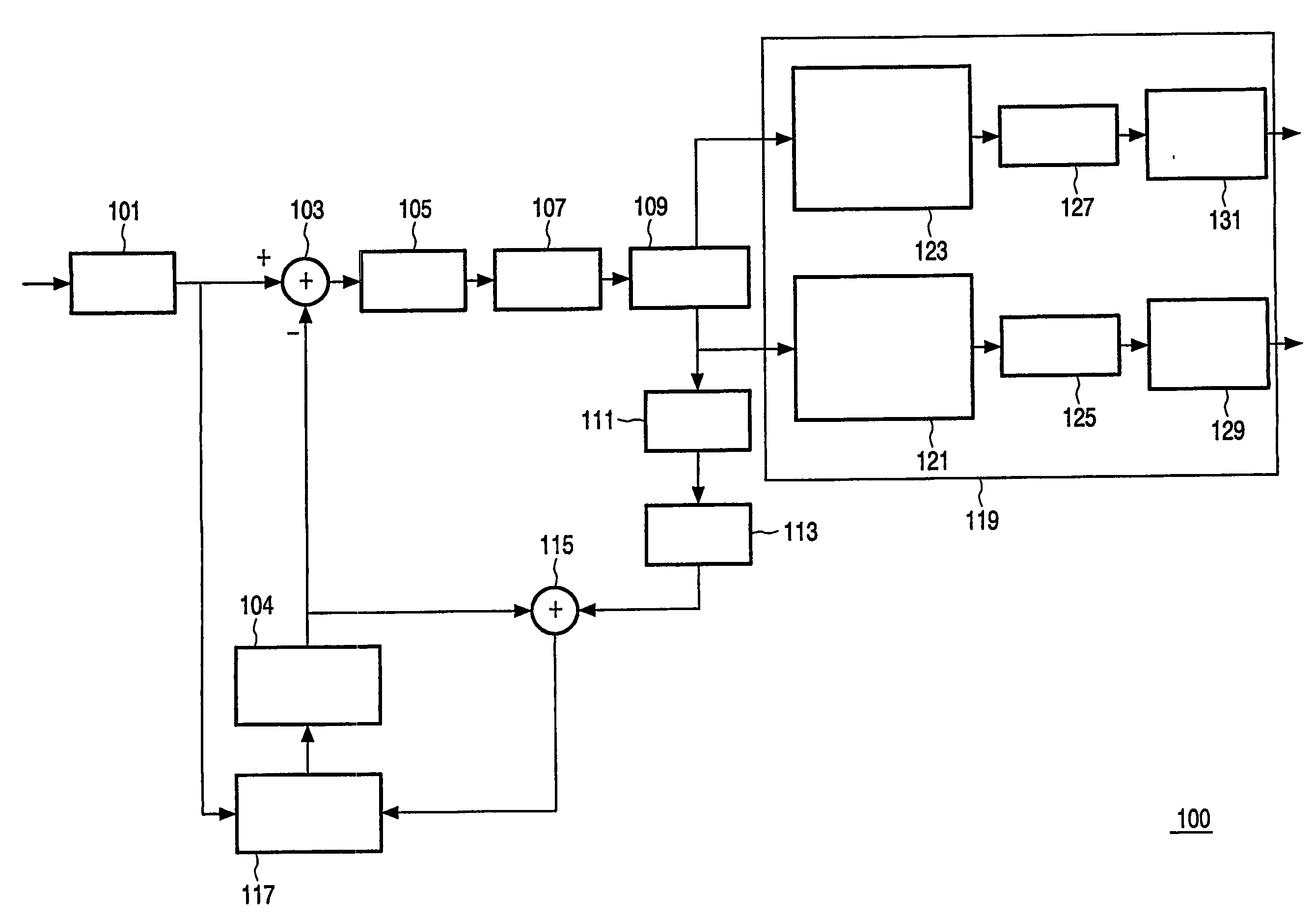
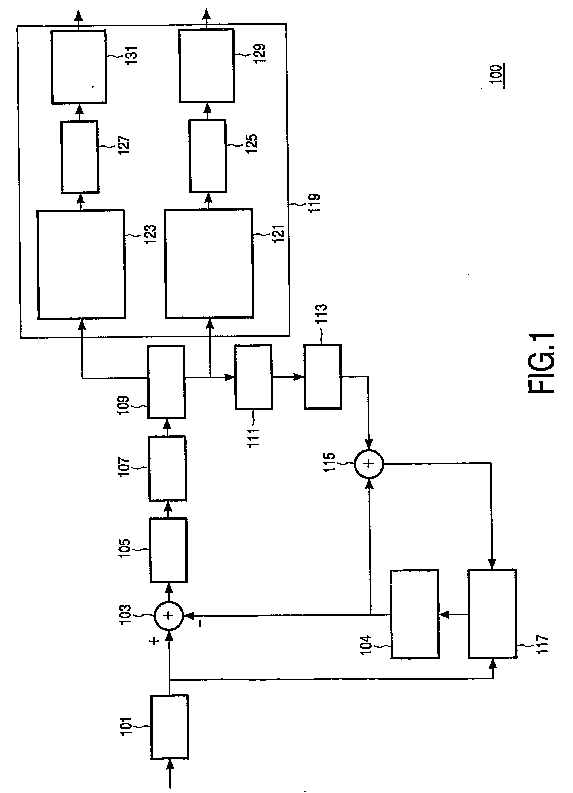
[0030]FIG. 1 is an illustration of a video encoder 100 in accordance with a preferred embodiment of the invention.

[0031] The video encoder 100 comprises a receiver 101 for receiving video frames. In the preferred embodiment, the video receiver is simply a functional block providing a suitable interface to a video source (not shown), which produces the video frames to be encoded. Depending on the application, the video source may for example be a video camera, a video storage unit, a video editing system or any other suitable means for providing video frames.

[0032] The video encoder 100 further comprises a first processor 103 for derivin


PUM


Abstract

A video encoder comprises a video frame receiver (101) connected to a processor (103) deriving relative frames from the received video frames and predicted frames. The processor is connected to a Discrete Fourier Transform (DCT) processor (105) which again is connected to a quantiser (107) for generating quantised spatial frequency coefficients for the relative frame. The output of the quantiser (107) is fed to a splitter that splits the data subset having low frequency components and a second data subset having frequency components. The first subset is used in the encoding loop comprising an inverse quantiser (111), inverse DCT processor (113), motion compensation processor (115, 117) and predicted frame processor (104). Hence, the encoding loop is simplified by only considering a reduced data set for each frame. A transmitter (119) transmits the video data as a progressively scalable stream for both the first and second data subsets.

Description


Claims


Application Information

Patent Timeline
Owner KONINKLIJKE PHILIPS ELECTRONICS NV
Why Eureka
Try Eureka