Endoscopic system equipped with gas supply apparatus
- Summary
- Abstract
- Description
- Claims
- Application Information
AI Technical Summary
Benefits of technology
Problems solved by technology
Method used
Image

Examples
Example
First Embodiment
[0051] Referring to FIGS. 1 to 5, an endoscopic system, equipped with a gas supply apparatus, of a first embodiment according to the present invention is described below.
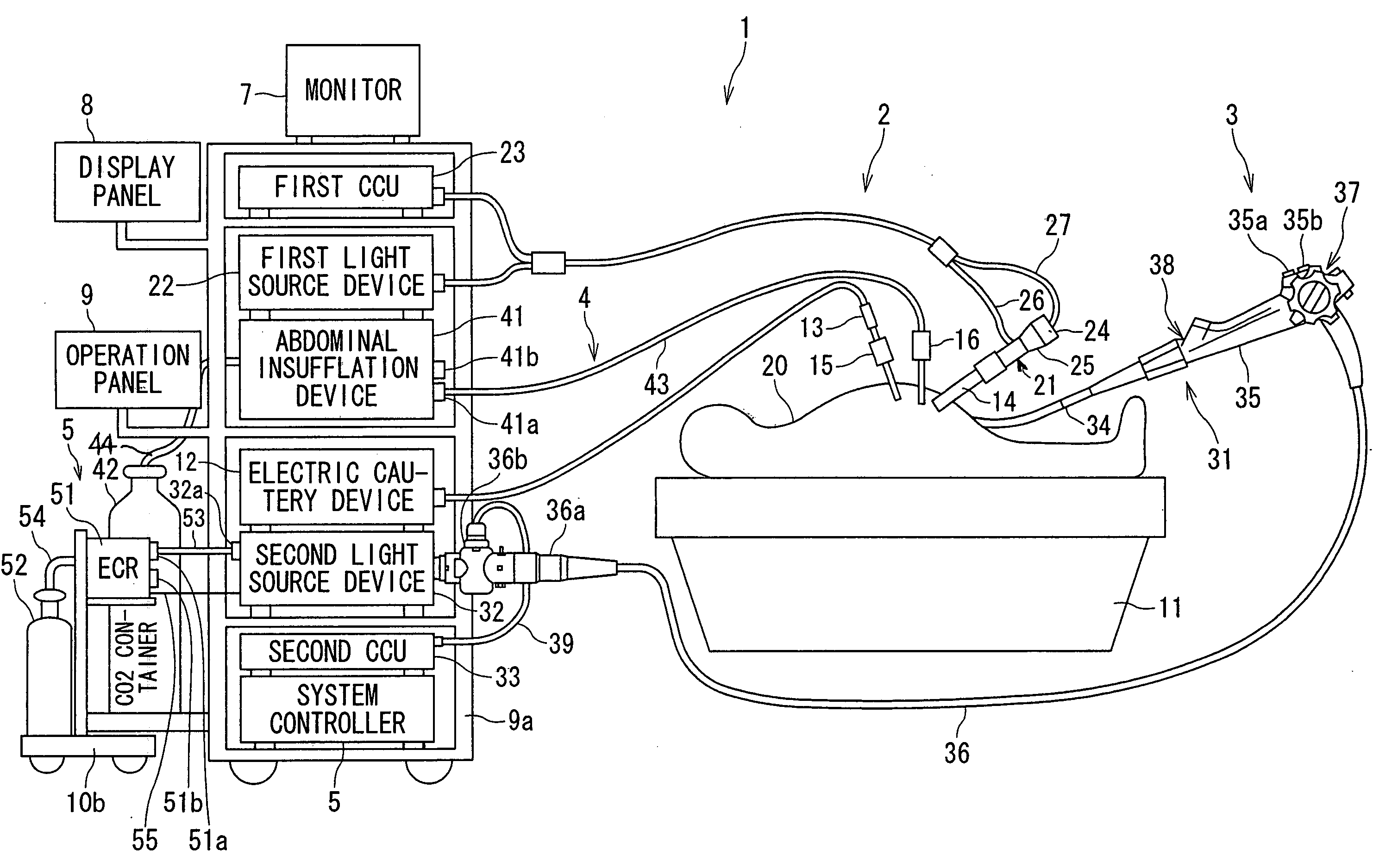
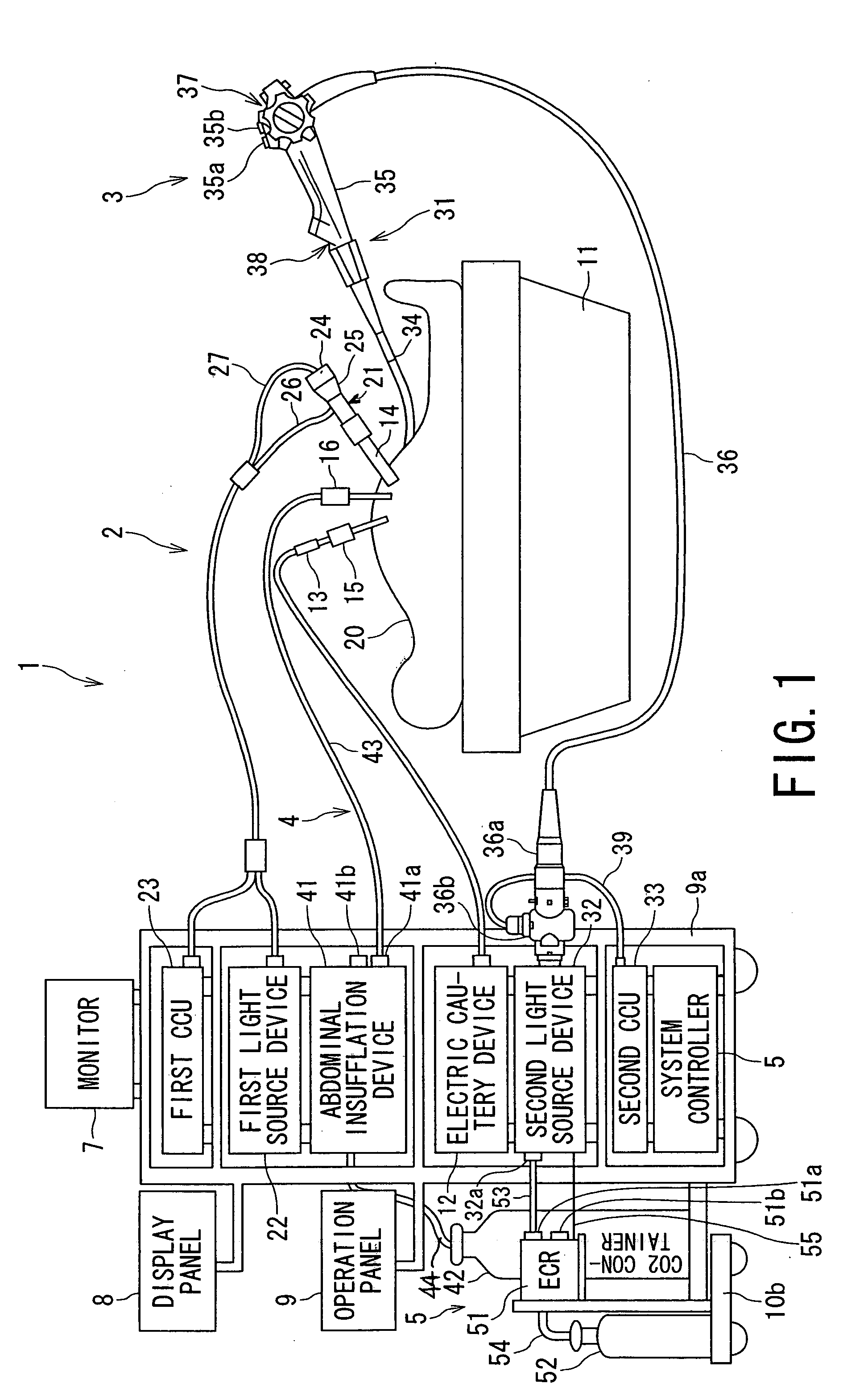
[0052] As shown in FIG. 1, with the presently filed embodiment, the endoscopic system of the present invention is implemented as a laparoscopic surgery operation system (hereinafter referred to as a surgery operation system) 1. The surgery operation system 1 is mainly comprised of component parts, such as a first endoscopic system 2, a second endoscopic system 3, a first gas supply apparatus 4, a second gas supply apparatus 5, a system controller 6, a monitor 7 serving as a display device, a centralized display panel 8, a centralized operation panel 9 and carts 10a, 10b.
[0053] Also, as shown in FIG. 1, reference numeral 11 designates an operation bed on which a patient 20 lies down. Reference numeral 12 designates an electric cautery device. Connected to the electric cautery device 12 is an electric
Example
Second Embodiment
[0106] Referring to FIGS. 6 and 7, an endoscopic system, equipped with the gas supply apparatus, of a second embodiment according to the present invention is described.
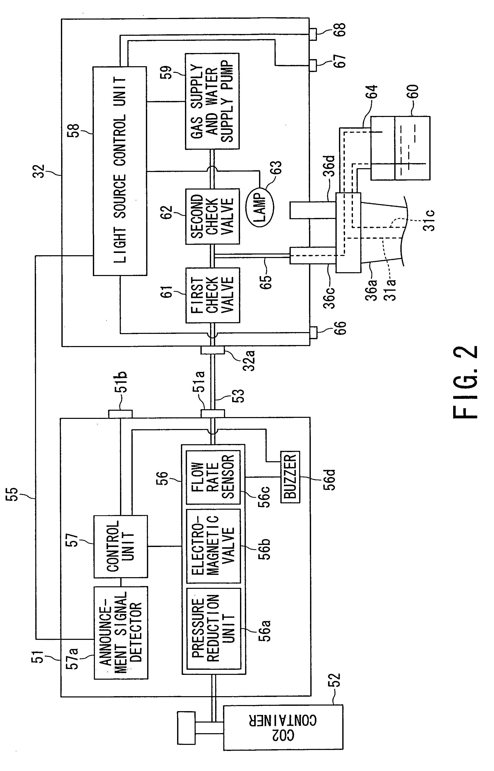
[0107] With the present embodiment, in place of electrically connecting the second light source device 32 and the ECR 51 through the communication cable 55, the abdominal insufflation device 41 and the ECR 51 are electrically connected through the communication cable 55. In addition, the presently filed embodiment takes the form of a structure wherein during a condition in which the abdominal insufflation device 41 is rendered operative, an abdominal cavity control unit 41c, provided in the abdominal insufflation device 41 and serving as a signal output means, outputs an abdominal cavity signal as an operation control signal, which serves as an announcement signal indicative of the abdominal insufflation device 41 remaining under the operative state, to the announcement signal detector 57a provided in
Example
Third Embodiment
[0128] Referring to FIG. 9, an endoscopic system, equipped with a gas supply apparatus, of a third embodiment according to the present invention is described.
[0129] As shown in FIG. 9, with the present embodiment, the second light source device 32 incorporates a light source connector detection sensor 69, serving as a connection status discriminating unit, which detects whether or not there is a status under which the light source connector 36d is connected to the second light source device 32. The light source connector detection sensor 69 may include a sensor of, for instance, an optical type or contact type and electrically connected to the light source control unit 58. Other structures are similar to those of the first embodiment and the same component parts bear like reference numerals to omit redundant description.
[0130] With such a structure of the presently filed embodiment, under a condition where the light source connector 36d is connected to the second lig
PUM
 Abstract
Description
Claims
Application Information
 - R&D Engineer
- R&D Manager
- IP Professional
- Industry Leading Data Capabilities
- Powerful AI technology
- Patent DNA Extraction
Browse by: Latest US Patents, China's latest patents, Technical Efficacy Thesaurus, Application Domain, Technology Topic.
© 2024 PatSnap. All rights reserved.Legal|Privacy policy|Modern Slavery Act Transparency Statement|Sitemap