Printing apparatus and printing method
a printing apparatus and printing method technology, applied in the direction of printing, other printing apparatus, etc., can solve the problems of deteriorating conveying accuracy, barely changing from the conventional manner, and high technical and cost constraints of the ejection orifice itsel
- Summary
- Abstract
- Description
- Claims
- Application Information
AI Technical Summary
Benefits of technology
Problems solved by technology
Method used
Image

Examples
first embodiment
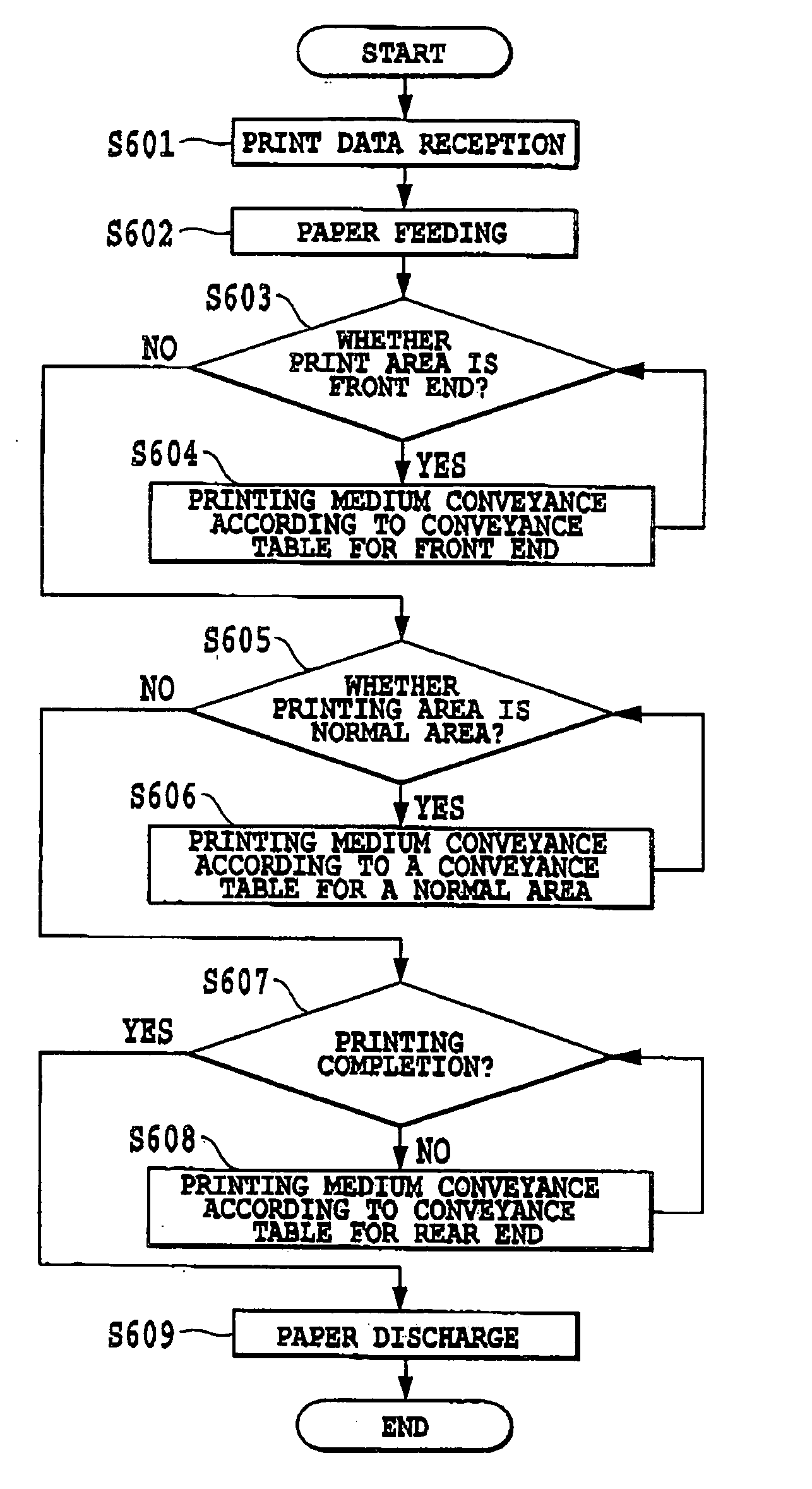
[0091]FIG. 12 is a flow chart showing a printing operation according to the first embodiment of the present invention, especially showing conveying processing of the printing medium. In FIG. 12, the same step numbers are given to steps which are the same as those described with reference to FIG. 3, and descriptions thereof are omitted.
[0092] Differences from processing shown in FIG. 3 are processing of steps S603a and S605a. In the step S603a, it is determined what a phase is in a conveying table at the time of transfer from the front end area to the normal area, and whether the phase Is a transfer Inhibition phase. That is, when the phase is any of phases 6 to 9 in the table shown in FIG. 7A, the phase is determined to be the transfer inhibition phase. When the phase is determined to be the transfer inhibition phase, a return is made to a step S604 to continue printing that uses the conveying table for the front end area. When the phase is determined not to be the transfer inhibition
second embodiment
[0094] In the first embodiment, it Is described how the present invention is applied to a transfer from the front end area to the normal area or the normal area to the rear end area. However, there is also a case where 1 / N (N=2 in FIG. 8B) deviation of a printing position in the sub-scanning direction with regard to the printing elements occurs when the range of the printing elements is returned after the skipping countermeasure processing. Even in such a case, similarly to the first embodiment, it is possible to prevent the deviation from occurring by providing a transfer inhibition phase.
[0095]FIG. 13 is a diagram showing conveying tables for the rear end area and for conveying of the return processing. In the conveying table according to which the range of printing elements to be used is returned (the range of printing elements to be used is changed), there is a difference in a phase 0 and a phase 2 from the conveying table for the rear end area shown in the FIG. 13, so that in t
third embodiment
[0097] Both in the first and second embodiments, transfer inhibition phases are provided. Therefore, a printing speed may decreases. More specifically, the number of printing elements to be used at the time of front end area printing is set to be smaller than the number of printing elements to be used at the time of normal area printing (front end area: 60, and normal area: 120 in example shown in FIG. 7A). As a transfer is made from the front end area to the normal area earlier, the earlier the number of printing elements to be used can be increased to be able to increase a printing speed. In the first and second embodiments, however, there is sometimes a case where a printing speed decreases because the transfer inhibition phases are provided to thereby delay transferring to the normal area from the front end area.
[0098]FIG. 7A is used as an example. After the printing medium is conveyed up to the phase 4 in the front end area, it is determined whether the phase 4 is the transfer in
PUM
 Abstract
Description
Claims
Application Information
 - R&D Engineer
- R&D Manager
- IP Professional
- Industry Leading Data Capabilities
- Powerful AI technology
- Patent DNA Extraction
Browse by: Latest US Patents, China's latest patents, Technical Efficacy Thesaurus, Application Domain, Technology Topic.
© 2024 PatSnap. All rights reserved.Legal|Privacy policy|Modern Slavery Act Transparency Statement|Sitemap