Combine dual auger unloader

a dual-auger, combine technology, applied in the field of combine or harvester, can solve the problems of reducing future crop yield, limited capacity of on-board primary storage hoppers, and insufficient capacity of no combine commercially available today, and achieves the effect of facilitating retrofitting and increasing unloading capacity

Active Publication Date: 2006-03-02
TRIBINE IND
View PDF7 Cites 9 Cited by
  • Summary
  • Abstract
  • Description
  • Claims
  • Application Information

AI Technical Summary

Benefits of technology

The technical effect that this patented technology has overcomes are its ability to increase the amount of material it can handle while also being able to easily replace older equipment used by farmers who use different types of harvesting machineries such as combine-grability bins and gravel trucks. This makes them more efficient than current options available at their disposal.

Problems solved by technology

The technical problem described in this patents is how to efficiently load upgrades without requiring excessive labor costs while minimizing negative effects caused by overloaded vehicles due to heavy loading requirements associated with increasingly greater ground speeds.

Method used


Image

  • Combine dual auger unloader
  • Combine dual auger unloader
  • Combine dual auger unloader

Examples


Embodiment Construction

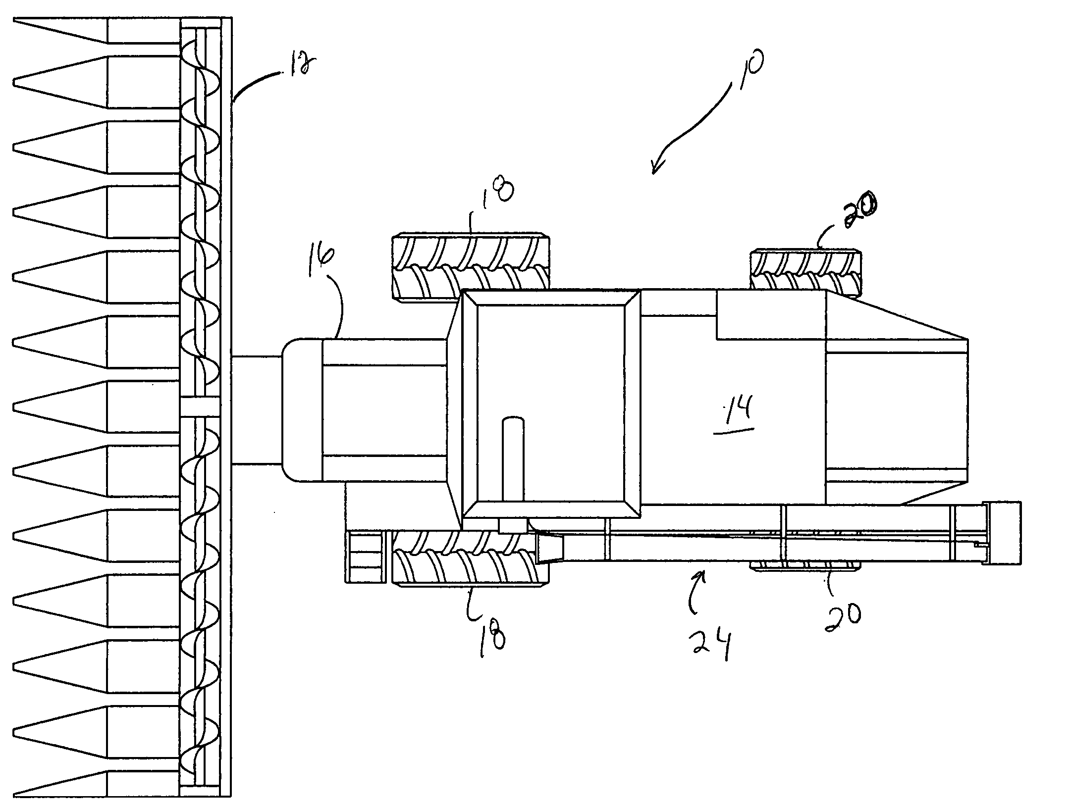
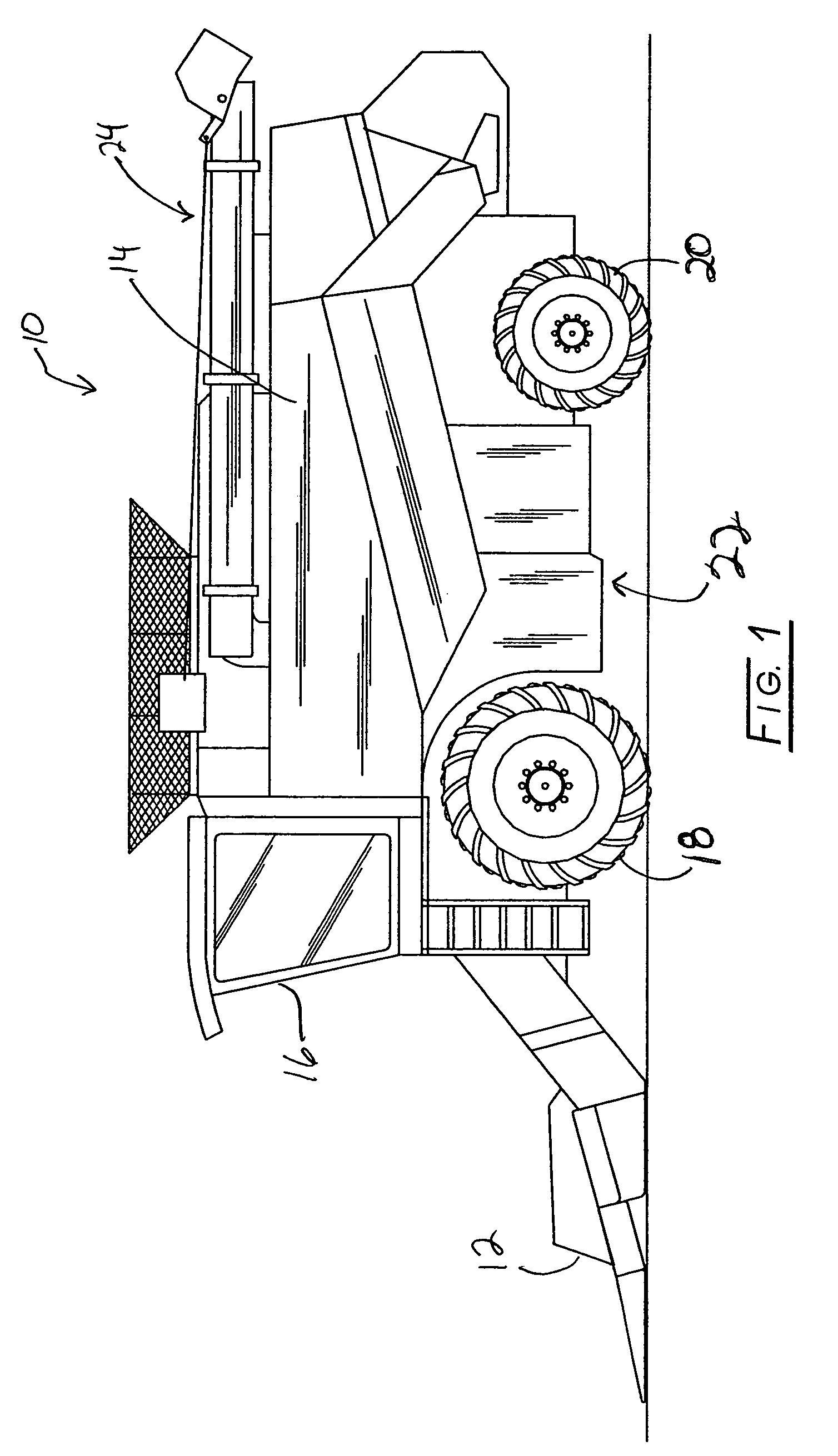
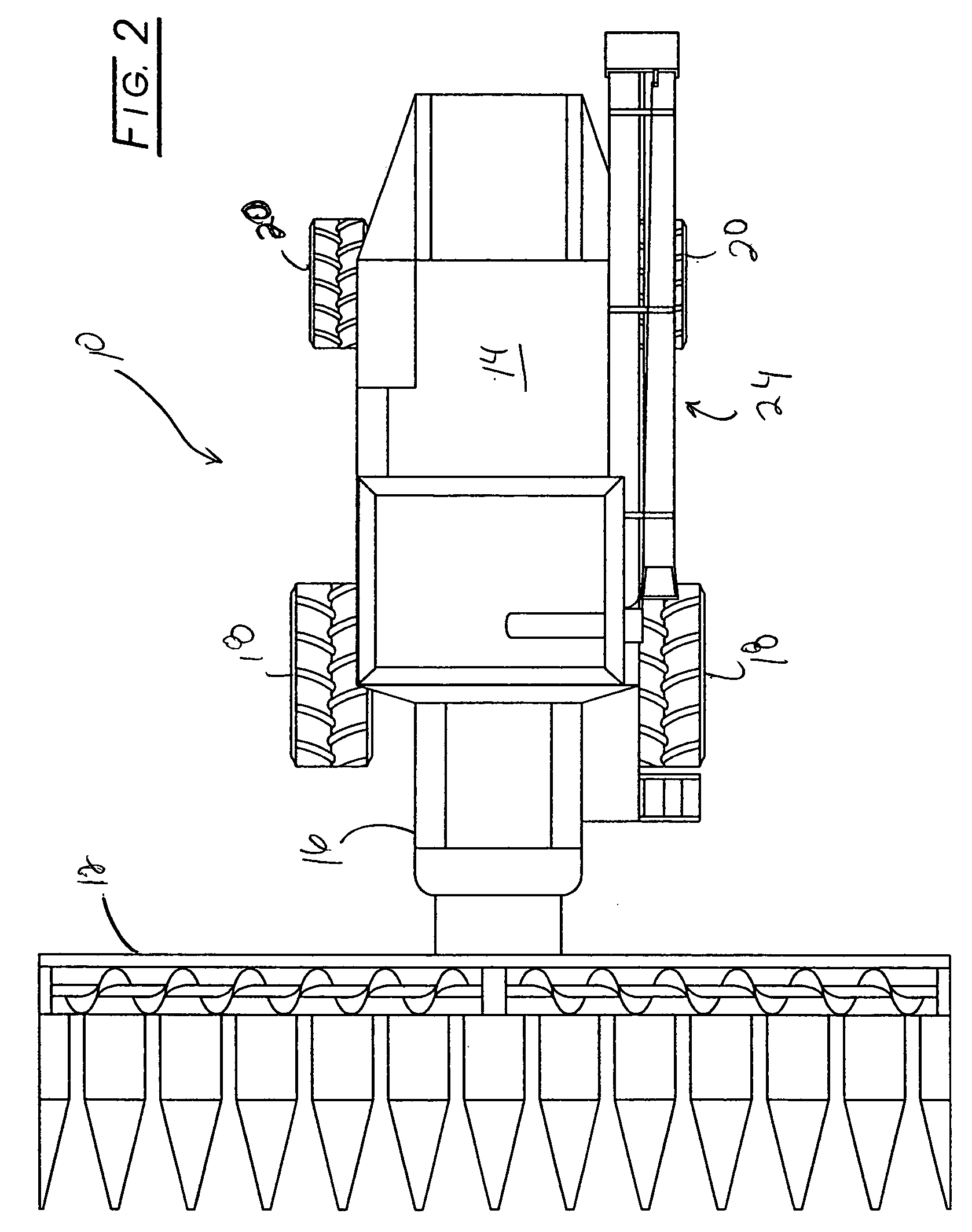
[0027] The present invention is addressed to unloading grain bins rapidly and has applicability to extra capacity grain bins, grain bins that receive more grain that their rated capacity, and the like. Such grain bins most often are carried by combines and grain carts. For present purposes combine and harvester are used interchangeably and no limitation should be implied by use of either term, as an apparatus that harvests grain in the field is broadly meant. So too, there no limitation of the term grain cart should be implied, as grain carts carry a grain bin and can be towed by a combine. Grain carts also can be powered and steerable, such as is disclosed in U.S. Pat. No. 5,904,365. While the invention can be applied to virtually any conventional combine, it has special applicability to combines having grain bins of up to 1000 to 1200 bushel or more capacity, such as are disclosed in one or more of the following patents: U.S. Pat. Nos. 6,012,272, 6,125,618, 6,339,917, 6,604,351, 6,60


PUM


Abstract

Disclosed is an improved grain unloader for off-loading (unloading) grain from a grain bin carried by one or more of a combine or a grain cart. A second grain movement assembly is coupled in parallel to the first grain movement assembly so that both grain movement assemblies can simultaneously off-load the grain bin. A third grain movement assembly feeds the second grain movement assembly. The first and second grain movement assemblies move together from a stowage position to an unloading position. The third grain assembly can only feed the second grain transfer assembly when the second grain assembly is in the off-load position.

Description


Claims


Application Information

Patent Timeline
Owner TRIBINE IND
Why Eureka
Try Eureka