Disk device

Inactive Publication Date: 2006-04-13
HITACHI CONSUMER ELECTRONICS CORP
View PDF9 Cites 3 Cited by
  • Summary
  • Abstract
  • Description
  • Claims
  • Application Information

AI Technical Summary

Benefits of technology

[0015] As set forth above, the disk device is arranged not only to be loaded with plural kinds of optical disks but also to select a proper recording format for one kind of disk and a recording method according to the kind of data to be recorded. However, if the disk device is arranged to process plural kinds of optical disks and use plural recording formats, it is preferable to shorten the time taken until recording of a certain amount of data is completed without selecting and changing the kind and the method of the rotation control in recording the data. Even the system disclosed in JP-A-8-22676 does not suppose the information recording that requires more strict laser intensity control or rotation control. Further, the JP-A-8-22676 discloses only the operation of accessing data on a disk from the inner periphery to the outer periphery or vice versa. Hence, the disk device arranged to treat plural kinds of optical disks and use plural recording formats needs a considerably long time until recording of a certain amount of data is completed.
[0016] It is an object of the present invention to provide a disk device that is arranged to treat plural kinds of optical disks and to use plural recording formats and enables to rapidly comp

Problems solved by technology

In addition to the replacement procedure caused by a defect, considering the characteristics of the DVD Video Recording format, when data is ofte

Method used


Image

  • Disk device
  • Disk device
  • Disk device

Examples


Embodiment Construction

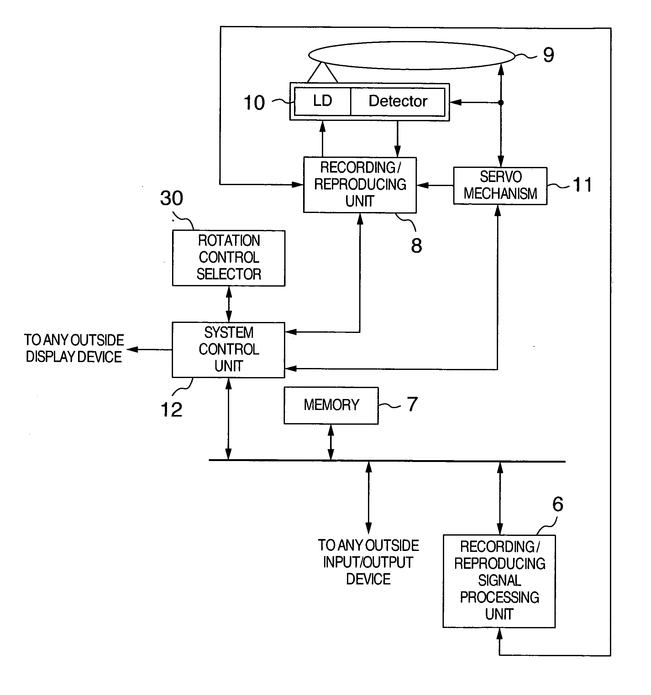
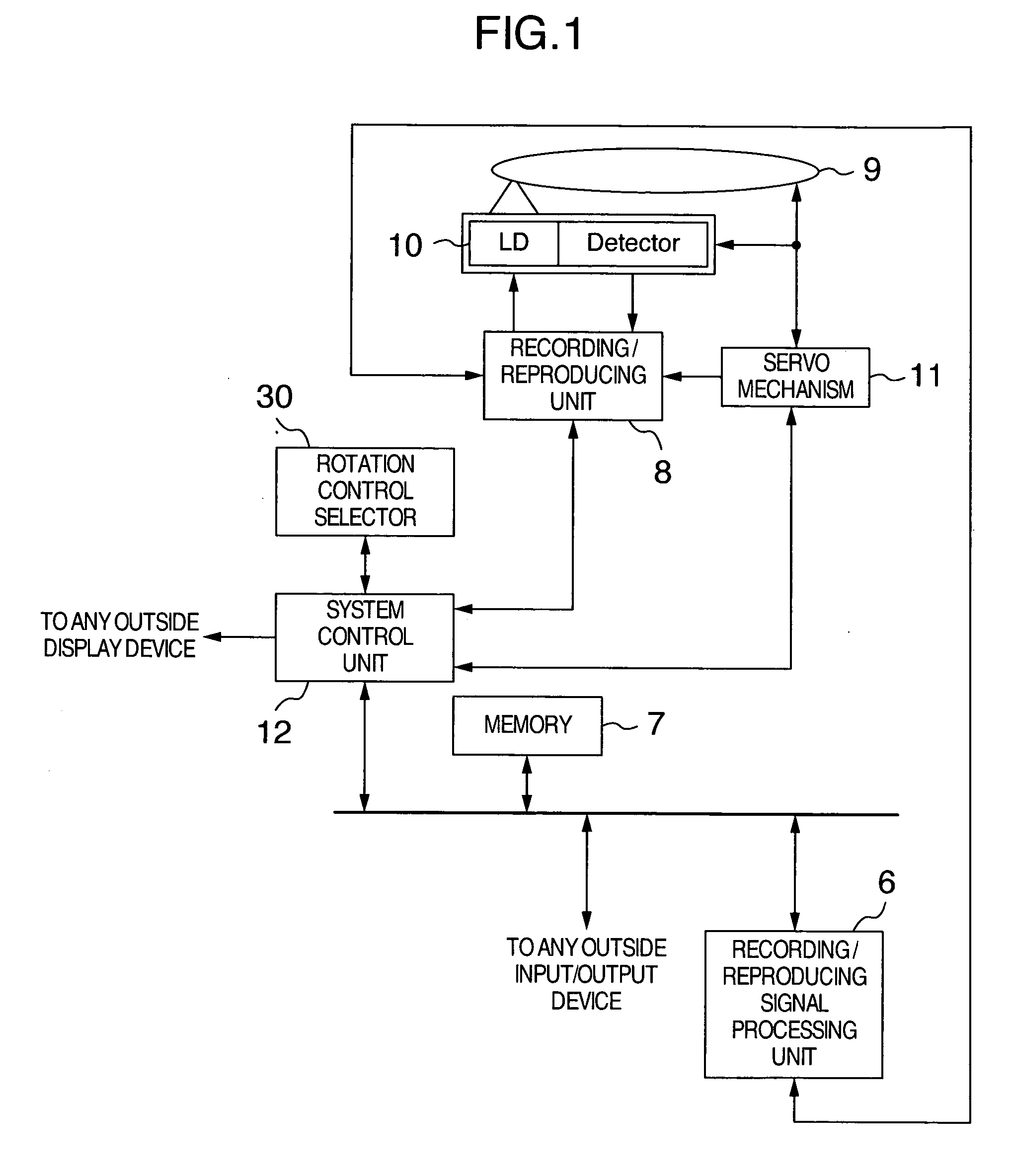
[0022] The embodiment of the present invention will be described with reference to FIGS. 1 and 2. FIG. 3 is a block diagram showing a schematic arrangement of an overall device to which a disk drive of the present invention is applied.

[0023] In FIG. 3, a numeral 1 denotes an imaging unit, which is composed of an imaging optical system 2, a charge-coupled device (CCD) 3 and an A / D converter 4. A subject is imaged on the CCD 3 through the imaging optical system 2. The CCD 3 outputs the corresponding image signal with the imaged subject to the A / D converter 4, which digitizes the image signal and then outputs to an image signal processing unit 5. The image signal processing unit 5 operates to convert the image signal sent from the imaging unit 1 into the corresponding image data. This image signal processing unit 5 also has a role of processing a voice signal sent from a microphone 14 served as a voice signal input device.

[0024] When reproducing the image data, the image signal proc


PUM


Abstract

A disk device is arranged to select an appropriate rotation control method according to a kind of an optical disk, a recording format or a recording method so that a recording operation for a certain amount of information may be completed as fast as possible, even if a waiting time takes place until the rotation is set. The disk device includes a unit for selecting the rotation control method for recording a certain amount of information more efficiently and rapidly in light of time according to a kind of an optical disk, a recording format or a recording method. The selected rotation control method is executed to control the rotation of the optical disk when recording information on the disk.

Description


Claims


Application Information

Patent Timeline
Owner HITACHI CONSUMER ELECTRONICS CORP
Why Eureka
Try Eureka