Optical fiber making apparatus and method
- Summary
- Abstract
- Description
- Claims
- Application Information
AI Technical Summary
Benefits of technology
Problems solved by technology
Method used
Image

Examples
first embodiment
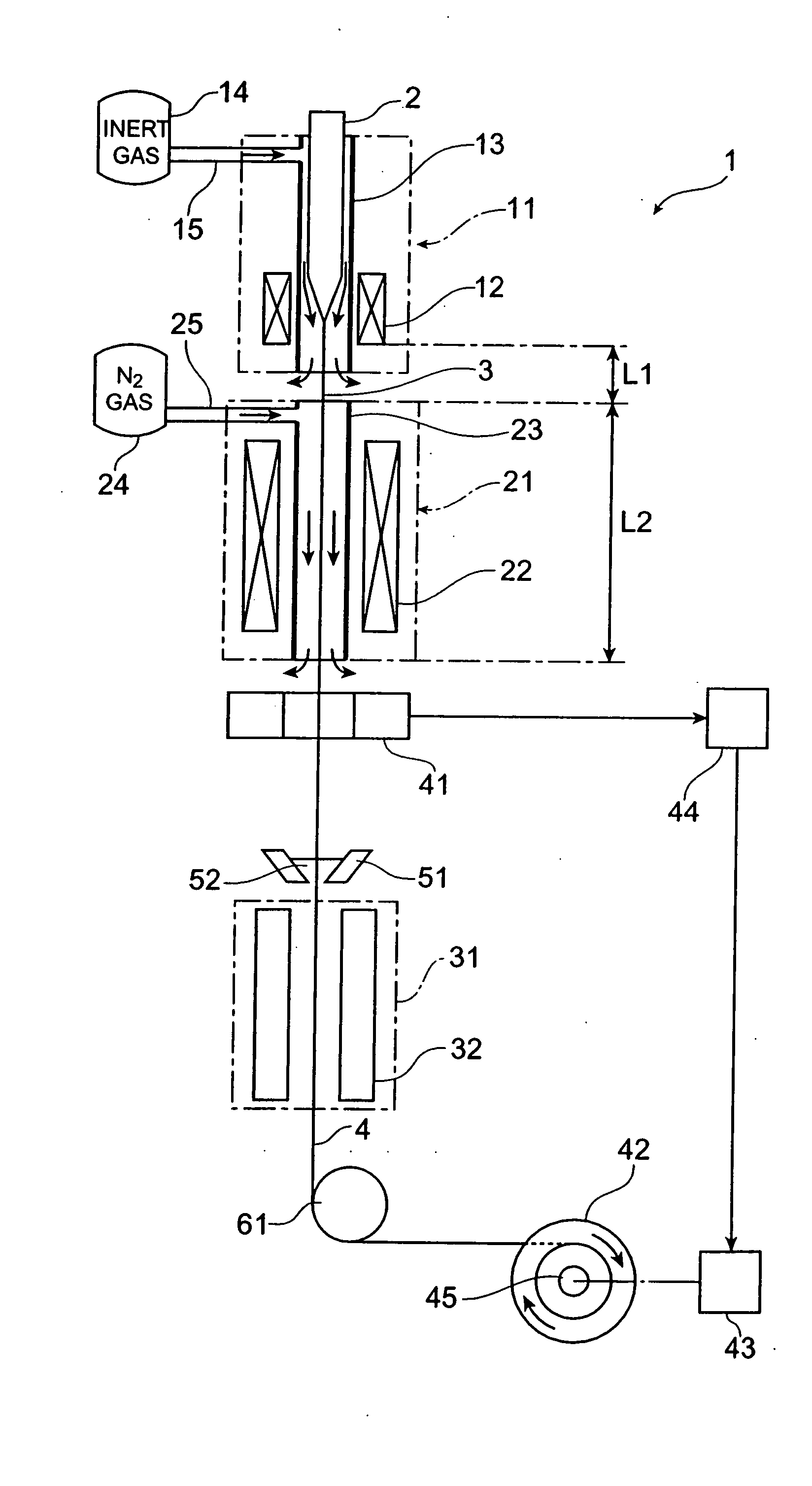
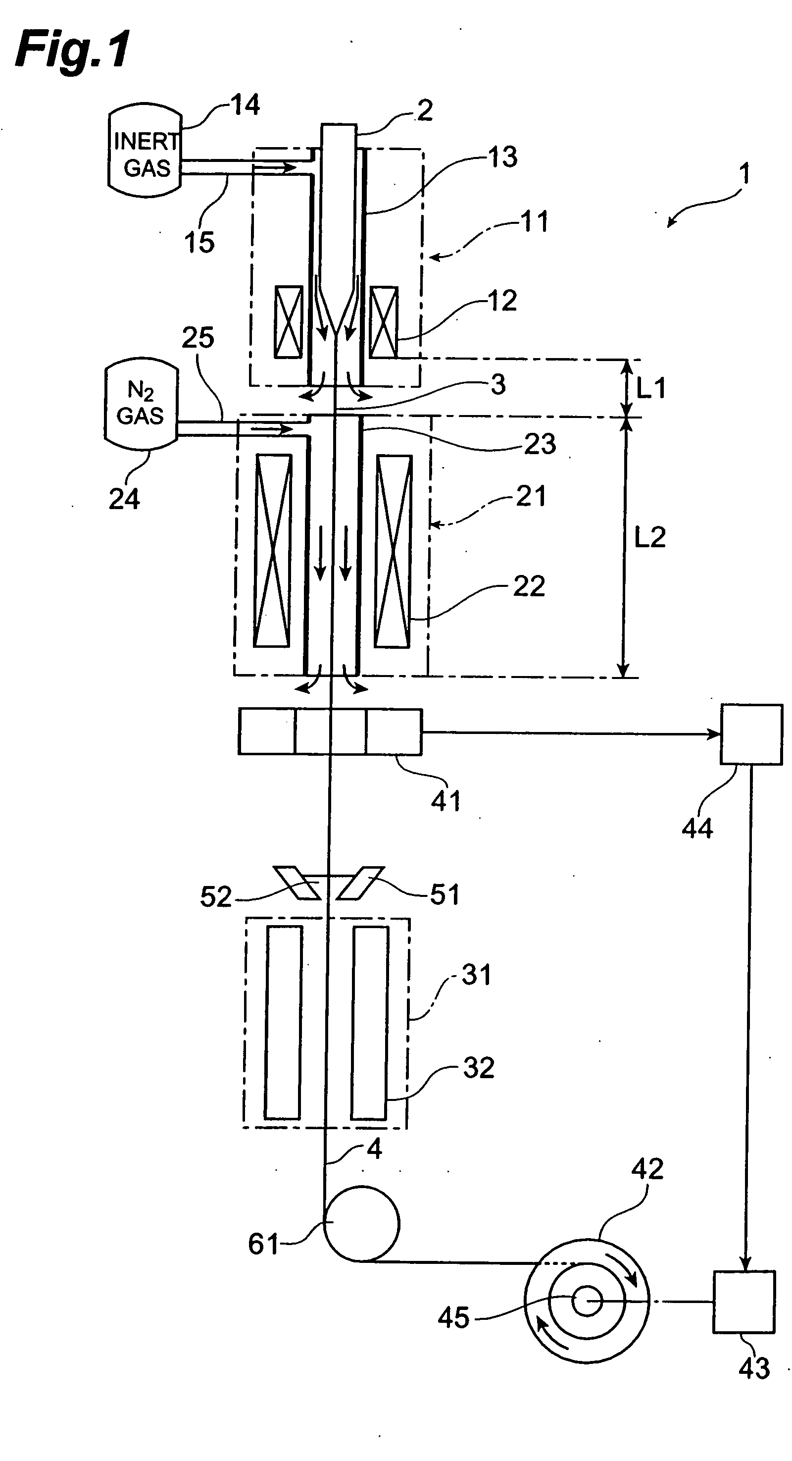
[0053] To begin with, a first embodiment of the apparatus and method for making an optical fiber in accordance with the present invention will be explained.
[0054] A drawing apparatus 1 is an apparatus for drawing silica type optical fiber; and comprises a drawing furnace 11, a heating furnace 21 for annealing, and a resin curing section 31, which are disposed in this order in the direction of drawing an optical fiber preform 2 (from the upper side to the lower side in FIG. 1). The optical fiber preform 2 held by a preform supplying apparatus (not depicted) is supplied to the drawing furnace 11, and the lower end of the optical fiber preform 2 is heated and softened by a heater 12 within the drawing furnace 11, so as to draw an optical fiber 3. An inert gas supply passage 15 from an inert gas supply section 14 is connected to a muffle tube 13 of the drawing furnace 11, so that an inert gas atmosphere is attained within the muffle tube 13 of drawing furnace 11. The optical fiber 3 drawn
example 1
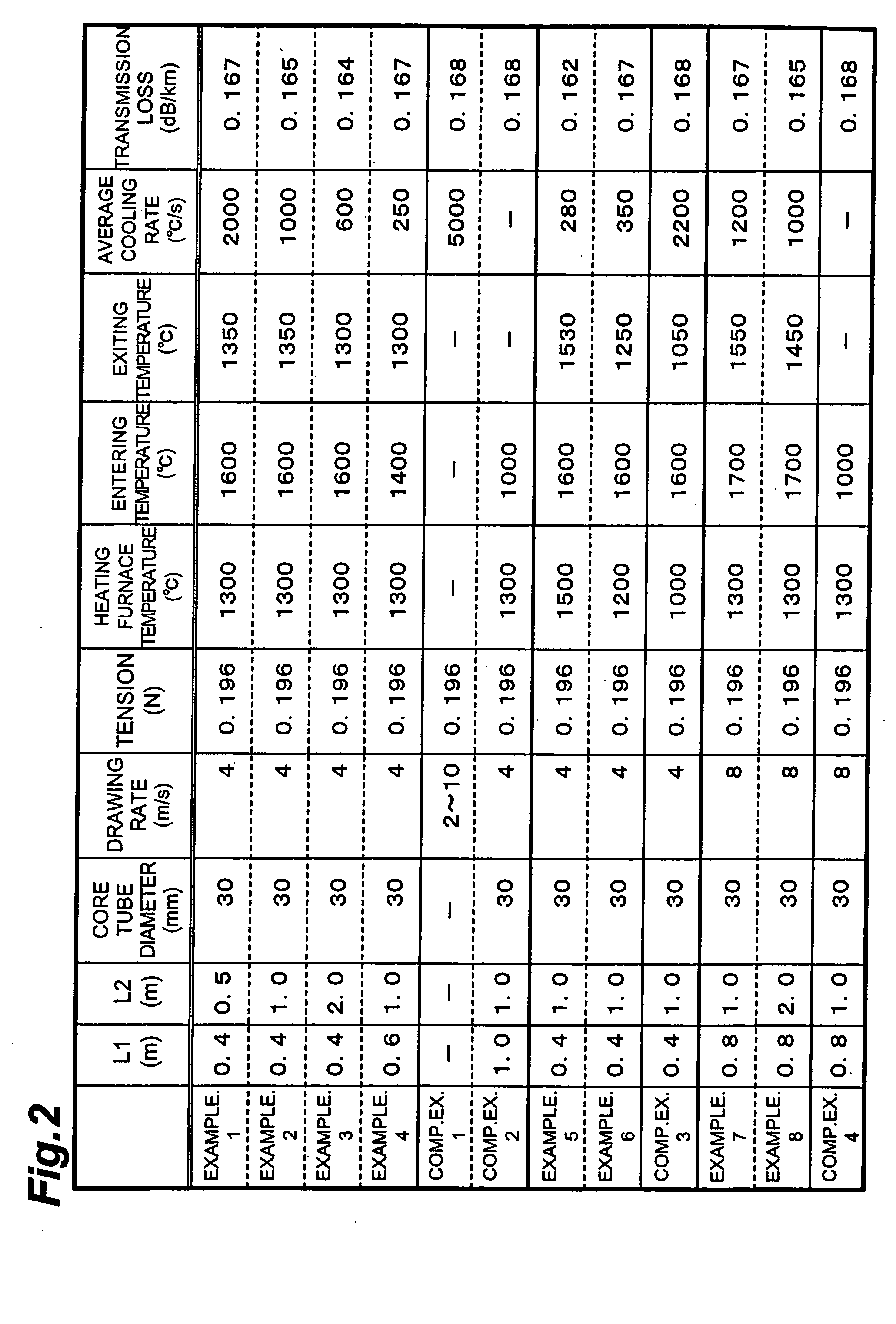
[0065] Using a heating furnace having a muffle tube (with an inner peripheral diameter of about 30 mm) in which L1=0.4 m and L2=0.5 m, an optical fiber was drawn. The optical fiber preform to be drawn had a core portion made of pure silica glass and a cladding portion made of fluorine-doped glass. The drawing rate, the drawing tension, and the temperature of heating furnace (temperature at the furnace center) were set to 4 m / s, 0.196 N (20 gf), and 1300° C., respectively. In this case, the temperature of the optical fiber immediately before entering the heating furnace (entering temperature) was 1600° C. in terms of the surface temperature of optical fiber, whereas the temperature of the optical fiber immediately after exiting from the heating furnace was 1350° C. in terms of the surface temperature of optical fiber. Hence, in the heating furnace, the part attaining a temperature of 1600 to 1350° C. in the drawn optical fiber is assumed to have been cooled at an average annealing rat
example 2
[0067] Using a heating furnace having a muffle tube (with an inner peripheral diameter of about 30 mm) in which L1=0.4 m and L2=1.0 m, an optical fiber was drawn. The optical fiber preform to be drawn had a core portion made of pure silica glass and a cladding portion made of fluorine-doped glass. The drawing rate, the drawing tension, and the temperature of heating furnace (temperature at the furnace center) were set to 4 m / s, 0.196 N (20 gf), and 1300° C., respectively. In this case, the temperature of the optical fiber immediately before entering the heating furnace (entering temperature) was 1600° C. in terms of the surface temperature of optical fiber, whereas the temperature of the optical fiber immediately after exiting from the heating furnace was 1350° C. in terms of the surface temperature of optical fiber. Hence, in the heating furnace, the part attaining a temperature of 1600 to 1350° C. in the drawn optical fiber is assumed to have been cooled at an average annealing rat
PUM
| Property | Measurement | Unit |
|---|---|---|
| Temperature | aaaaa | aaaaa |
| Temperature | aaaaa | aaaaa |
| Temperature | aaaaa | aaaaa |
Abstract
Description
Claims
Application Information
 - R&D Engineer
- R&D Manager
- IP Professional
- Industry Leading Data Capabilities
- Powerful AI technology
- Patent DNA Extraction
Browse by: Latest US Patents, China's latest patents, Technical Efficacy Thesaurus, Application Domain, Technology Topic.
© 2024 PatSnap. All rights reserved.Legal|Privacy policy|Modern Slavery Act Transparency Statement|Sitemap