Rotary actuator for an adjuster of a vehicle seat

a technology of rotary actuator and vehicle seat, which is applied in the direction of gearing, mechanical control devices, instruments, etc., can solve the problem of significant reduction of subjective impression of a large actuating path with low efficiency, and achieve the effect of lowering transmission ratio and high transmission ratio

Inactive Publication Date: 2006-06-15
KEIPER GMBH & CO KG
View PDF27 Cites 2 Cited by
  • Summary
  • Abstract
  • Description
  • Claims
  • Application Information

AI Technical Summary

Benefits of technology

This patented technology improves upon existing designs used for vehicles' seats that allow them to be easily controlled remotely or automatically. It includes a manual control mechanism operated by hand-held operation elements, a geared system where the input operates over time, and another device called an output unit connected to it. When activating this design, there can also vary its speed based on how fast they operate.

Problems solved by technology

This patented describes a problem where current designs have issues such as excessive wear or reduced effectiveness due to lacked space between certain components within the design's structure.

Method used


Image

  • Rotary actuator for an adjuster of a vehicle seat
  • Rotary actuator for an adjuster of a vehicle seat
  • Rotary actuator for an adjuster of a vehicle seat

Examples


Embodiment Construction

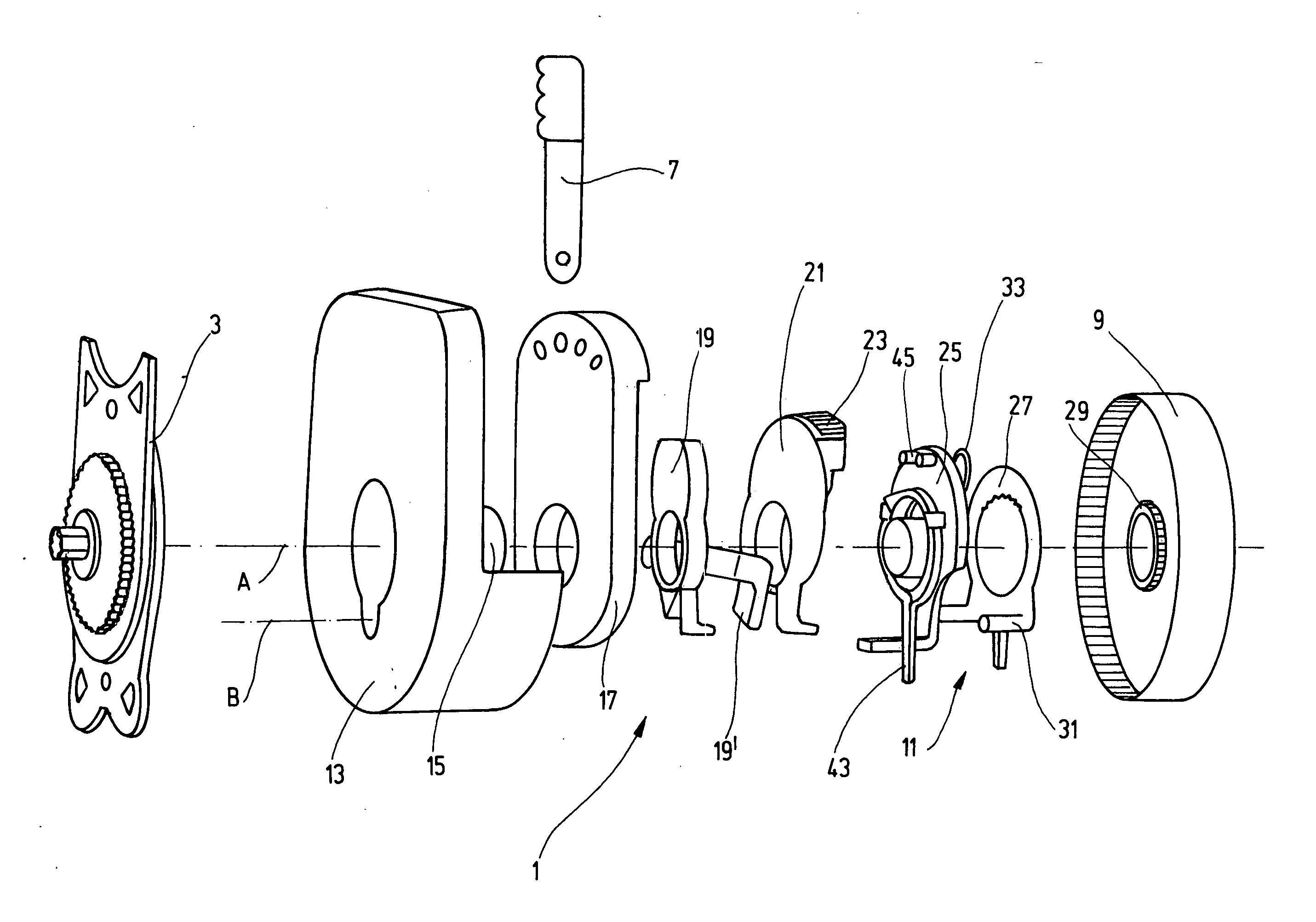
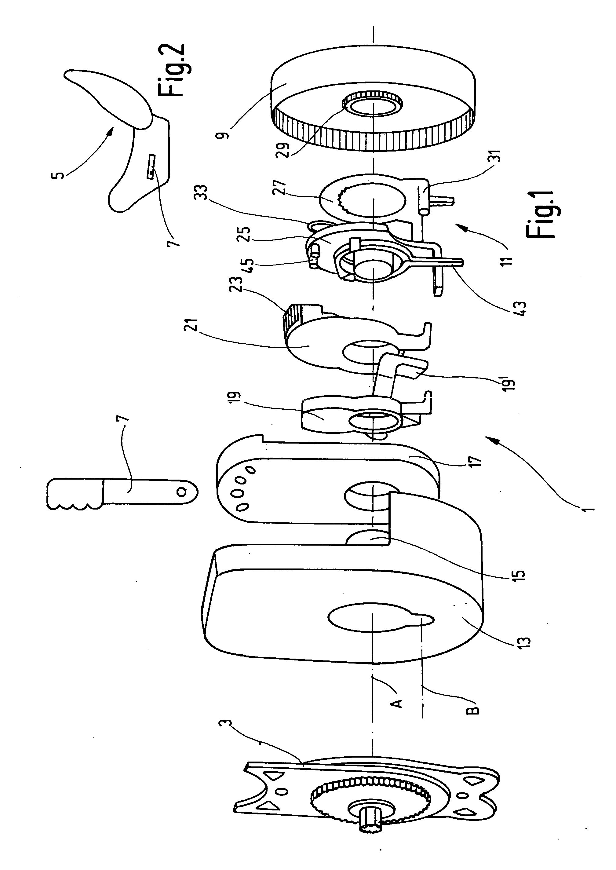
[0017] A manual rotary actuator 1, which is for actuating an adjuster 3 of a vehicle seat 5 in a motor vehicle, has a manually actuatable operating element 7 and an output element 9. In the present case, the operating element 7 is a hand lever. The output element 9 is in the form of a wheel that can be indirectly rotated in response to the operating element 7 being operated. The rotational movement of the output element 9 drives the adjuster 3. In accordance with the exemplary embodiment, the actuator 1 functions as a step-by-step mechanism for actuating a height adjuster. A transmission gearing 111 is arranged in the rotary actuator 1, operatively between the operating element 7 and the output element 9. In accordance with the invention, the transmission gearing 11 provides a high transmission ratio during an initial movement of the operating element 7 out of the inoperative position. This provision of the high transmission ratio during the initial movement of the operating element 7


PUM


Abstract

In the case of a rotary actuator for an adjuster of a vehicle seat, in particular of a motor vehicle seat, having a manually actuatable operating element (7), a transmission gearing (11) on which the operating element (7) acts when actuated, and an output element (9) which is rotated at least intermittently by the transmission gearing (11) and, during a rotation, drives the adjuster (3), the transmission gearing (11) changing during the actuation by the operating element (7) from a higher transmission ratio to a lower transmission ratio, during the actuation by the operating element (7) the transmission gearing (11) runs through two phases during which the transmission ratios are constant in each case.

Description


Claims


Application Information

Patent Timeline
Owner KEIPER GMBH & CO KG
Why Eureka
Try Eureka