Multi-threshold CMOS system and methods for controlling respective blocks

a technology of cmos and blocks, applied in the field of mtcmos system and methods for controlling respective blocks, can solve the problems of reducing the speed of transistors in the ic, increasing power consumption when the device is used, and reducing the power supply voltage, so as to prevent leakage current from the block

Active Publication Date: 2006-08-17
SAMSUNG ELECTRONICS CO LTD
View PDF5 Cites 2 Cited by
  • Summary
  • Abstract
  • Description
  • Claims
  • Application Information

AI Technical Summary

Benefits of technology

This patent describes a way to protect against leaks caused by electrical signals on electronic devices during normal operation. It suggests that if there are any issues or problems with certain parts of the device being used for communication, it can stop sending data through these areas instead of directly transmitting them over wires. Additionally, this technology helps improve the efficiency of power supply systems.

Problems solved by technology

The technical problem addressed by this patent is how to efficiently manage power usage during idle modes without sacrificing performance in normal operation modes that require more power.

Method used


Image

  • Multi-threshold CMOS system and methods for controlling respective blocks
  • Multi-threshold CMOS system and methods for controlling respective blocks
  • Multi-threshold CMOS system and methods for controlling respective blocks

Examples


Embodiment Construction

[0037] The present invention will now be described more fully hereinafter with reference to the accompanying drawings, in which exemplary embodiments of the invention are shown. The invention may, however, be embodied in different forms and should not be construed as limited to the embodiments set forth herein. Rather, these embodiments are provided so that this disclosure will be thorough and complete, and will fully convey the scope of the invention to those skilled in the art. In the figures, the dimensions of layers and regions are exaggerated for clarity of illustration. Like reference numerals refer to like elements throughout.

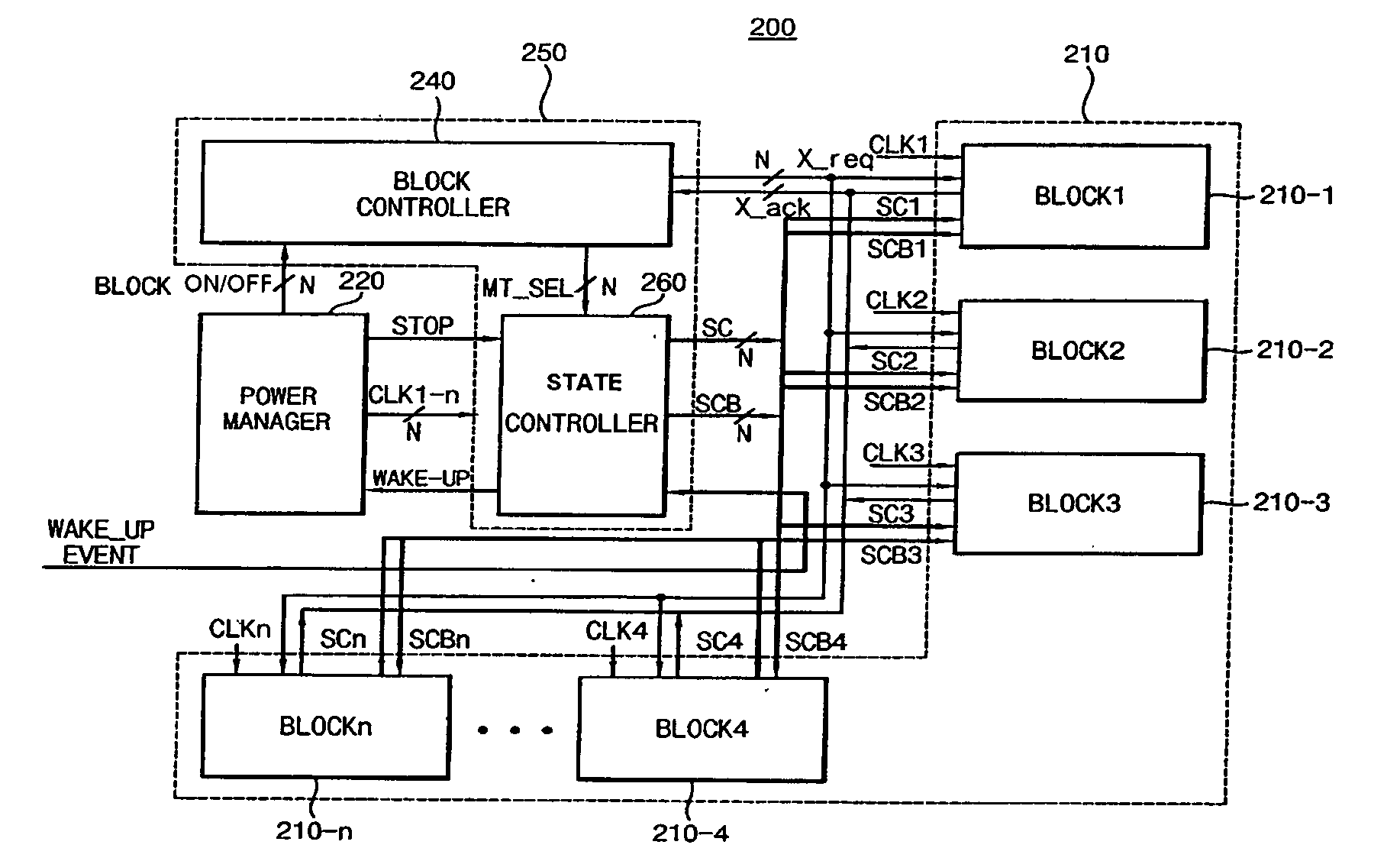
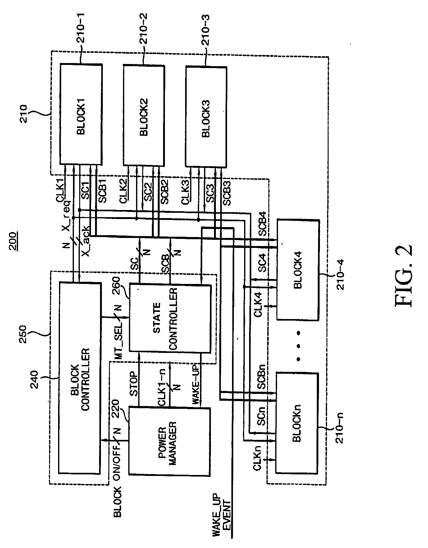
[0038]FIG. 2 illustrates an MTCMOS system 200 in accordance with an embodiment of the present invention. The MTCMOS system 200 may include a power manager 220, an MTCMOS controller block 250 including a block controller 240 and a state controller 260, and an MTCMOS design area 210 having a plurality of blocks 210-i.

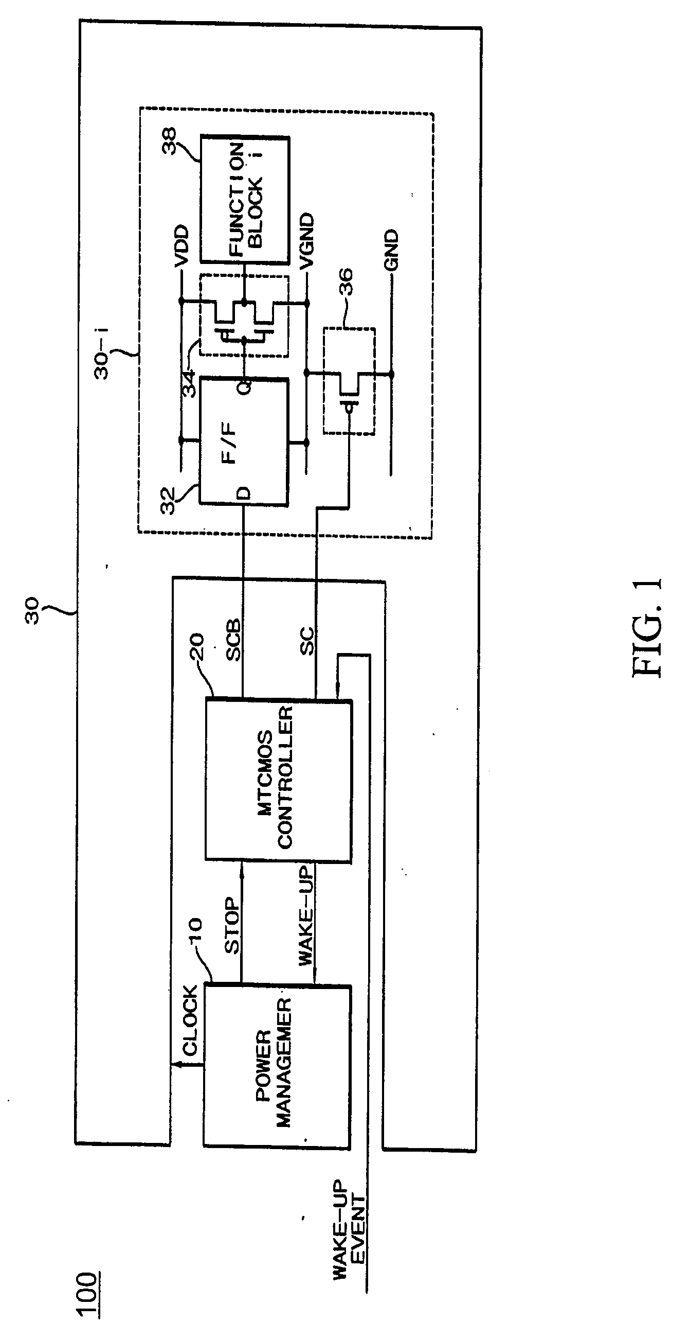
[0039] As can be seen in FIG. 3, each bl


PUM


Abstract

A multi-threshold CMOS system and method controls a state of respective blocks individually. Each block includes a logic circuit having a logic transistor and a control transistor connected between the logic circuit and a power line connected to one of a ground and a power source. The control transistor has a higher threshold than the logic transistor. The blocks are controlled by generating an individual block ON/OFF signal for each block, generating an individual control signal in response to the individual block ON/OFF signal, supplying the individual control signal to the control transistor and controlling voltage supply to the logic circuit within each block in accordance with the individual control signal.

Description


Claims


Application Information

Patent Timeline
Owner SAMSUNG ELECTRONICS CO LTD
Why Eureka
Try Eureka