High efficiency light fixture

Inactive Publication Date: 2006-09-14
HUPPI BRIAN +1
View PDF1 Cites 35 Cited by
  • Summary
  • Abstract
  • Description
  • Claims
  • Application Information

AI Technical Summary

Benefits of technology

[0011] The invention relates, in another embodiment, to a light fixture. The light fixture includes a lamp that emits light from a surface. The light fixture also includes a reflector arrangement that uniformly concentrates all the light emitted from the surface of the lamp to a target area. The reflector arrangement includes an outer reflector partially surrounding the lamp and defining an open end through which light emitted from the surface of the lamp and light reflected from the outer reflector travel out of the light fixture. The outer reflector includes a plurality of interconnected outer facets positioned in an arcuate manner such that the outer reflector flares outwardly from its center to its open end. Each of the outer facets has a flat mirrored surface that faces the lamp and that reflects all light incident thereon to the target area. The reflector arrangement also includes an inner reflector positioned at the open end of the outer reflector. The inner reflector captures stray light that is traveling in a direction away from the target area and redirects the stray light to the target area. The inner reflector includes a plurality of spaced apart and laterally positioned inner facets, each of the inner facets having flat mirrored surfaces on both of its sides that reflect all light incident thereon to the target area. In some cases, the light fixture may further include one or more partitions for helping support the inner facets and possibly helping direct some of the light towards the target area.

Problems solved by technology

Yet their inherent high efficiency has been wasted all these years by placing them in an inefficient luminaire, usually no more than a curved white rear ‘reflector’ or a white box with some form of lens.
No innovative designs appeared until the late 60's with the need to reduce glare in offices, by placing reflective grids in front of the tubes to direct some of the stray light in a more downward direction.
But the combined thickness of many reflector elements obstructing the output aperture, further reduced efficiency.
Next came light absorbing baffles in front of the tube to minimize stray light, but they restricted the direct downward light as well, and therefore, also reduced efficiency.
But the designs were hampered by three misunderstandings: (1) the belief that a luminaire must be shallow to follow current architectural and lighting concepts, (2) a lack of recognizing the difference between the behavior of output rays from a ‘point source’ (the hot filament inside a clear flashlight bulb), and a ‘distributed source’ (the glowing outer surface of the fluorescent tube itself), and (3), little interest in developing a technique for calculating or measuring the actual light output over a target area, an essential to guide the design efforts.

Method used


Image

  • High efficiency light fixture
  • High efficiency light fixture
  • High efficiency light fixture

Examples


Example

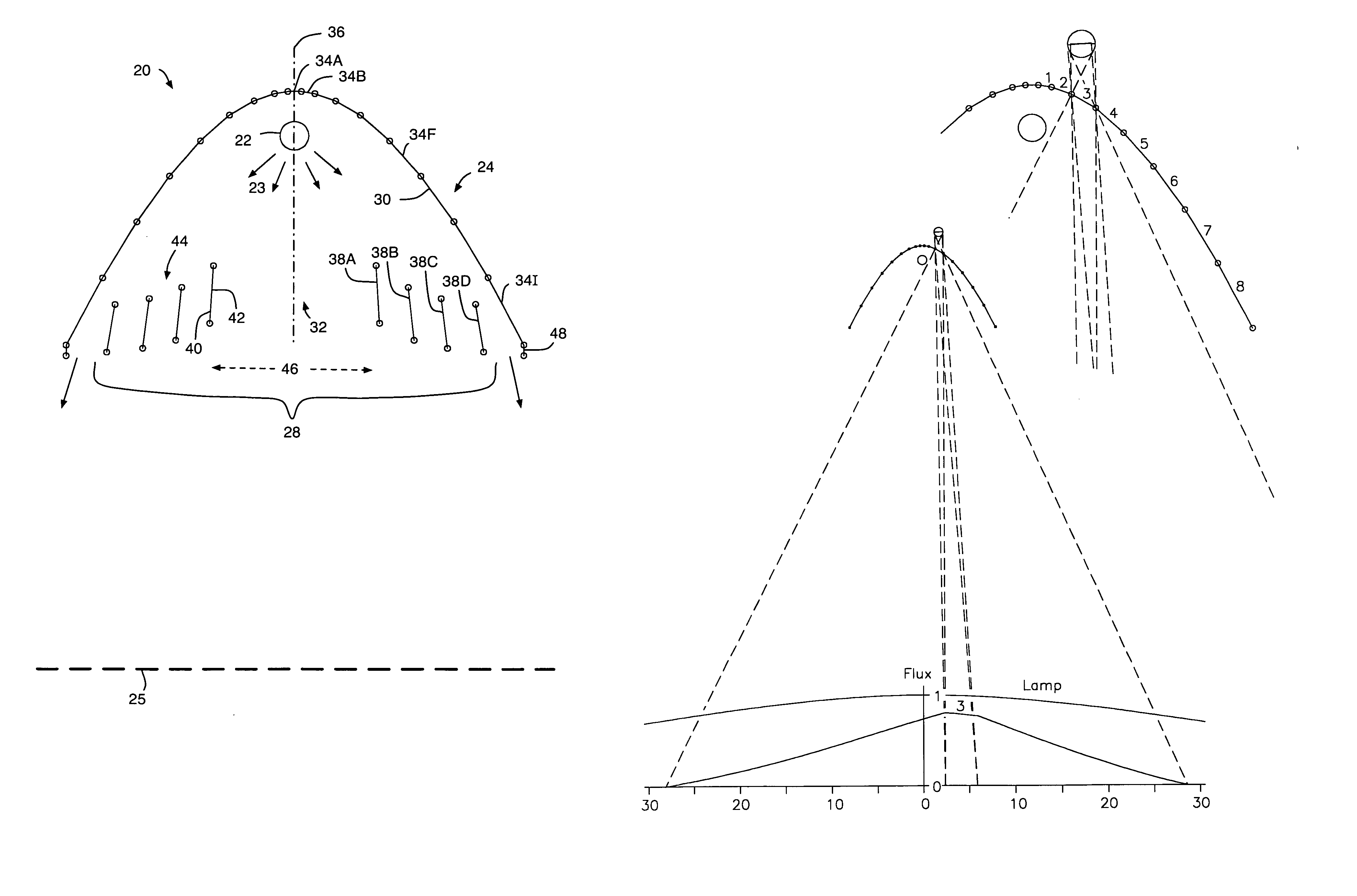
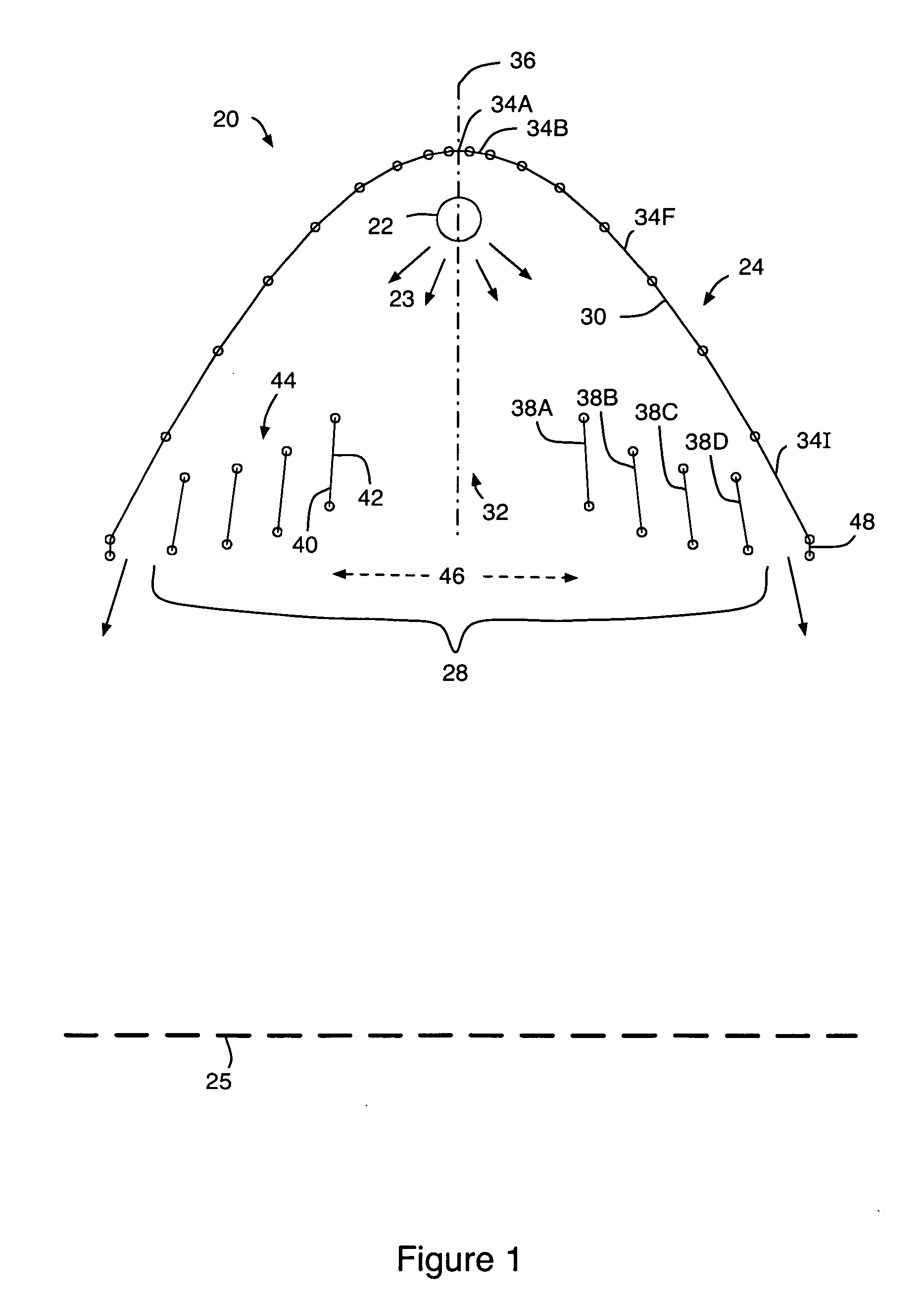
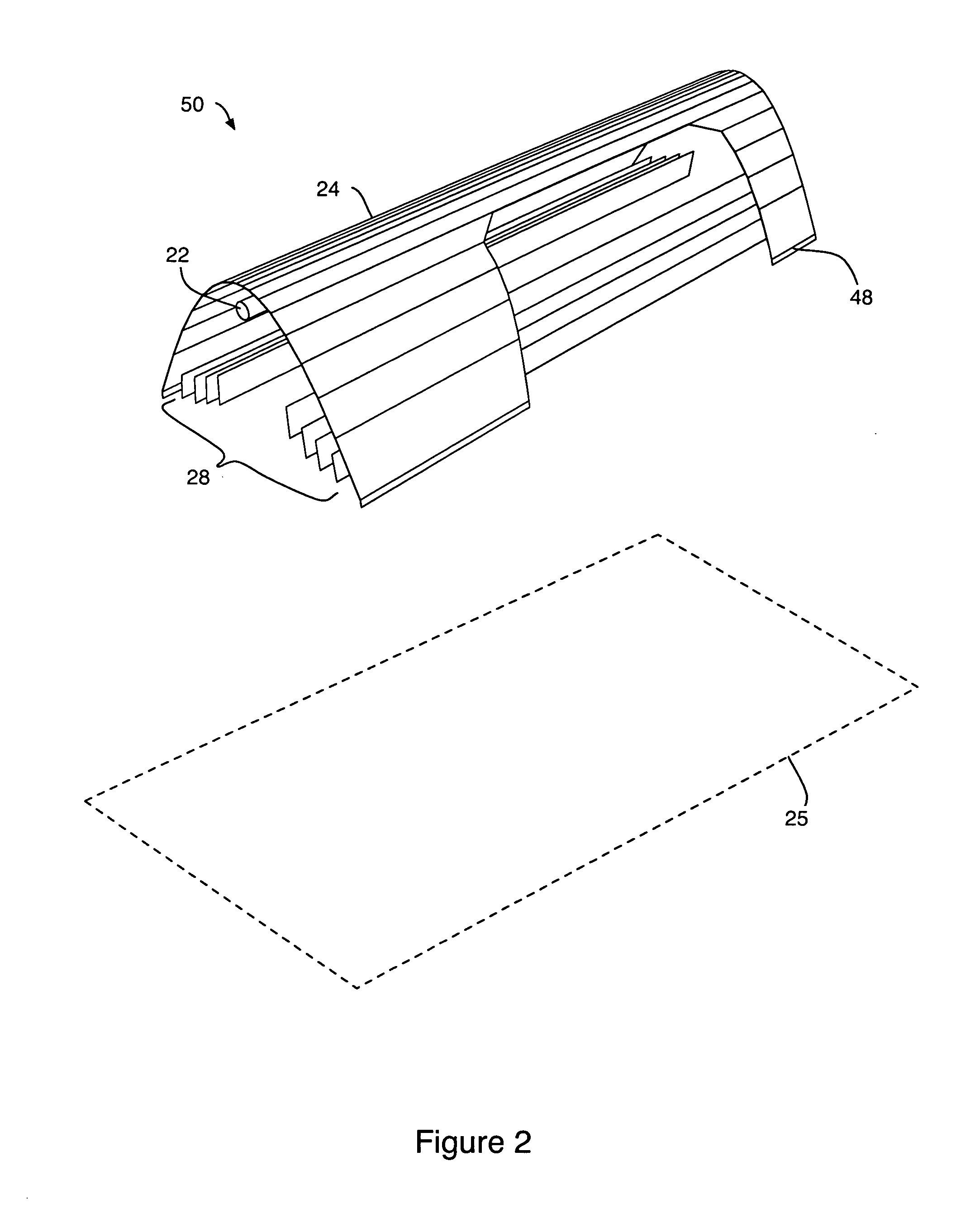
[0058] The present invention pertains to a high efficiency light fixture. One aspect of the invention relates to methods and apparatuses for directing a much greater percentage than attainable with prior art of the light generated therefrom within a specific target area. For example, the light fixture may include one or more reflectors for redirecting any light traveling away from the target area (e.g., stray light) back to the target area. In one embodiment, the light fixture includes an outer reflector for redirecting a first portion of the stray light to the target area and an inner reflector for redirecting the remaining portions of the stray light to the target area. In another embodiment, the light fixture includes one or more partitions for redirecting light end to end of the light fixture. Another aspect of the invention relates to methods and apparatuses for controlling the intensity and location of the light inside the specific target area. That is, the light made incident in


PUM


Abstract

A light fixture for illuminating a specific target area is disclosed. The light fixture includes an extended light source that emits light from a surface. The light source emits light from the surface in directions towards the target area and away from the target area. The light fixture also includes a reflector arrangement configured to redirect the light that would otherwise be emitted from the surface of the light source in directions away from the target area to directions towards the target area such that substantially all the light emitted from the light source is made incident in or directed into the target area.

Description


Claims


Application Information

Patent Timeline
Owner HUPPI BRIAN
Why Eureka
Try Eureka