Method for calculating a direct mode motion vector for a bi-directionally predictive-picture

a technology of motion vector and direct mode, applied in the field of direct mode motion vector calculation, can solve the problems of high power consumption, large number of operations and operation difficulty of hardware dividers, and loss of calculation accuracy, so as to reduce the number of operations and operation difficulty, the effect of reducing the number of operations

Inactive Publication Date: 2007-01-25
PANASONIC CORP
View PDF5 Cites 22 Cited by
  • Summary
  • Abstract
  • Description
  • Claims
  • Application Information

AI Technical Summary

Benefits of technology

This patented describes an improved way to calculate moving objects by comparing their movement with certain mathematical models that are used during simulations or experiments. These methods have similarities from both specifications but they can be easier to perform because there's no extra steps needed compared to previous versions. Additionally, these techniques reduce computational time while maintaining accurate results even if some parts get lost due to errors caused by factors like temperature changes overtime. Overall, it makes computing faster and more efficient on computers.

Problems solved by technology

This patented technical solution describes how video coding standards allow videos without interference to neighbor frames but still allows them to match up together smoothly due to their content being included temporarily instead of continuously repeating across entire scenes. By performing calculations based upon previous frame data rather than relying solely on pixel differences, the computational complexity becomes smaller while maintaining image resolution.

Method used


Image

  • Method for calculating a direct mode motion vector for a bi-directionally predictive-picture
  • Method for calculating a direct mode motion vector for a bi-directionally predictive-picture
  • Method for calculating a direct mode motion vector for a bi-directionally predictive-picture

Examples


Embodiment Construction

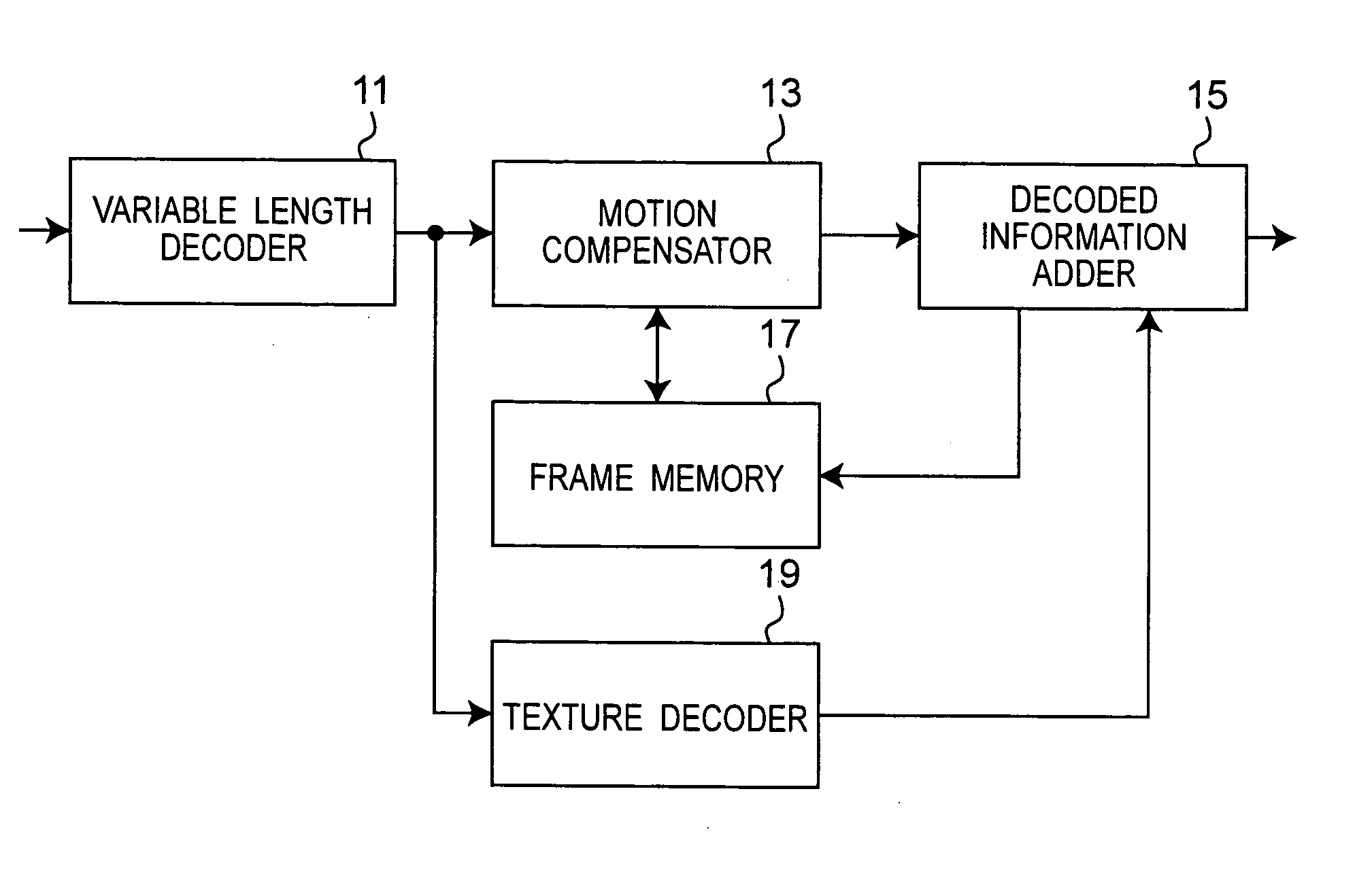
[0040] Referring to FIG. 5, a block diagram of a MPEG-4 decoder according to a preferred embodiment of this invention is shown. In processes for decoding pictures, a bit stream is input to a variable length decoder 11, and then the variable length decoder 11 decodes encoded data. The decoded data includes information on the encryption mode, i.e. Intra or Inter, for each macro block.

[0041] When the information on the encryption mode for a macro block indicates Intra, the encoded data may be decoded and output directly from a texture decoder 19. On the other hand, when the information on the encryption mode for the macro block indicates Inter, a motion compensator 13 generates a predictive frame based on motion compensation vectors, and then the generated predictive frame is added to an output from the texture decoder 19 in a decoded information adder 15 and output therefrom. The components of the MPEG-4 decoder according to the preferred embodiment of this invention may be embodied by


PUM


Abstract

A method for calculating a direct mode motion vector for a bi-directionally predictive-picture includes: calculating S based on TRB, TRD, and N; calculating Tx based on MVx, the S, and the N; calculating Ty based on MVy, the S, and the N; obtaining a sum of the Tx, MVDx and δ1x, and using the obtained sum as MVFx; obtaining a sum of the Ty, MVDy and δ1y, and using the obtained sum as MVFy; obtaining a sum of the MVFx, δ2x, and a minus value of the MVx, and using the obtained sum as MVBx; and, obtaining a sum of the MVFy, δ2y, and minus value of the MVy, and using the obtained sum as MVBy.

Description


Claims


Application Information

Patent Timeline
Owner PANASONIC CORP
Why Eureka
Try Eureka