Secure trash container assembly

Inactive Publication Date: 2007-06-21
SUNCAST
View PDF26 Cites 16 Cited by
  • Summary
  • Abstract
  • Description
  • Claims
  • Application Information

AI Technical Summary

Benefits of technology

[0021] A further objective is to provide a trash container having panels with integrated connectors which

Problems solved by technology

One drawback associated with this type of container occurs when the filled liner engages the side walls of the container.
This engagement often causes difficulty in removing the filled bags from the container.
Typically, the aforementioned one-piece containers are large and incapable of being knocked-down for shipping and storage, adding additional expense to the producer and thus the consumer.
However, the nested containers are bulky and heavy, offering marginal gains to an end consumer.
These types of containers suffer from numerous drawbacks for consumers.
One such drawback relates to assembly of the container.
These containers are often difficult to assemble, requiring tools and a substantial number of fasteners to align the panels and doors for proper operation.
In addition, such containers may require internal linkages for operation of the lid.
Typically, the structure of such devices are complex, requiring numerous small metal and/or plastic fasteners and connector members to maintain a structurally sound

Method used


Image

  • Secure trash container assembly
  • Secure trash container assembly
  • Secure trash container assembly

Examples


Embodiment Construction

[0046] While the present invention is susceptible of embodiment in various forms, there is shown in the drawings and will hereinafter be described a presently preferred embodiment with the understanding that the present disclosure is to be considered an exemplification of the invention and is not intended to limit the invention to the specific embodiments illustrated.

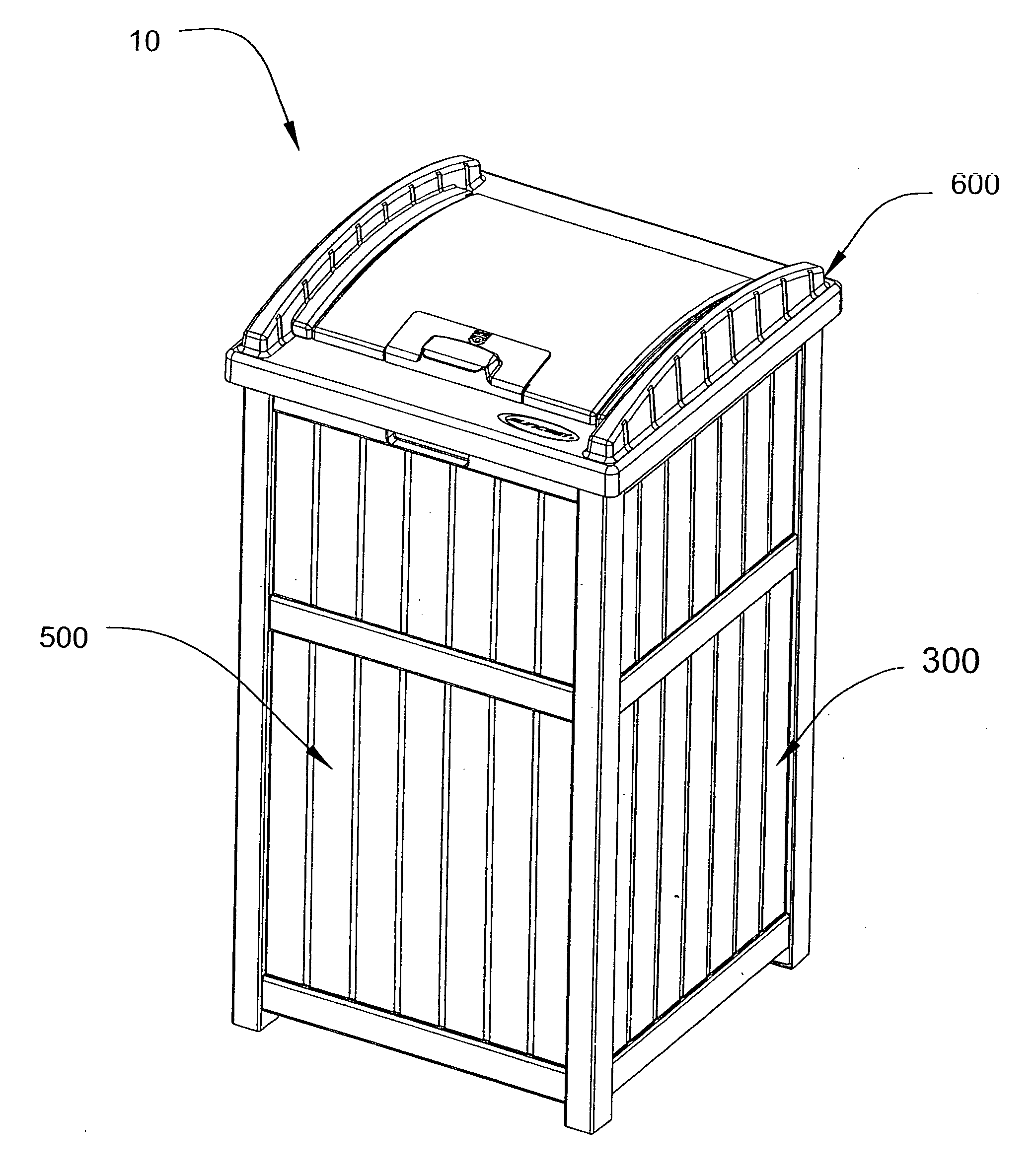
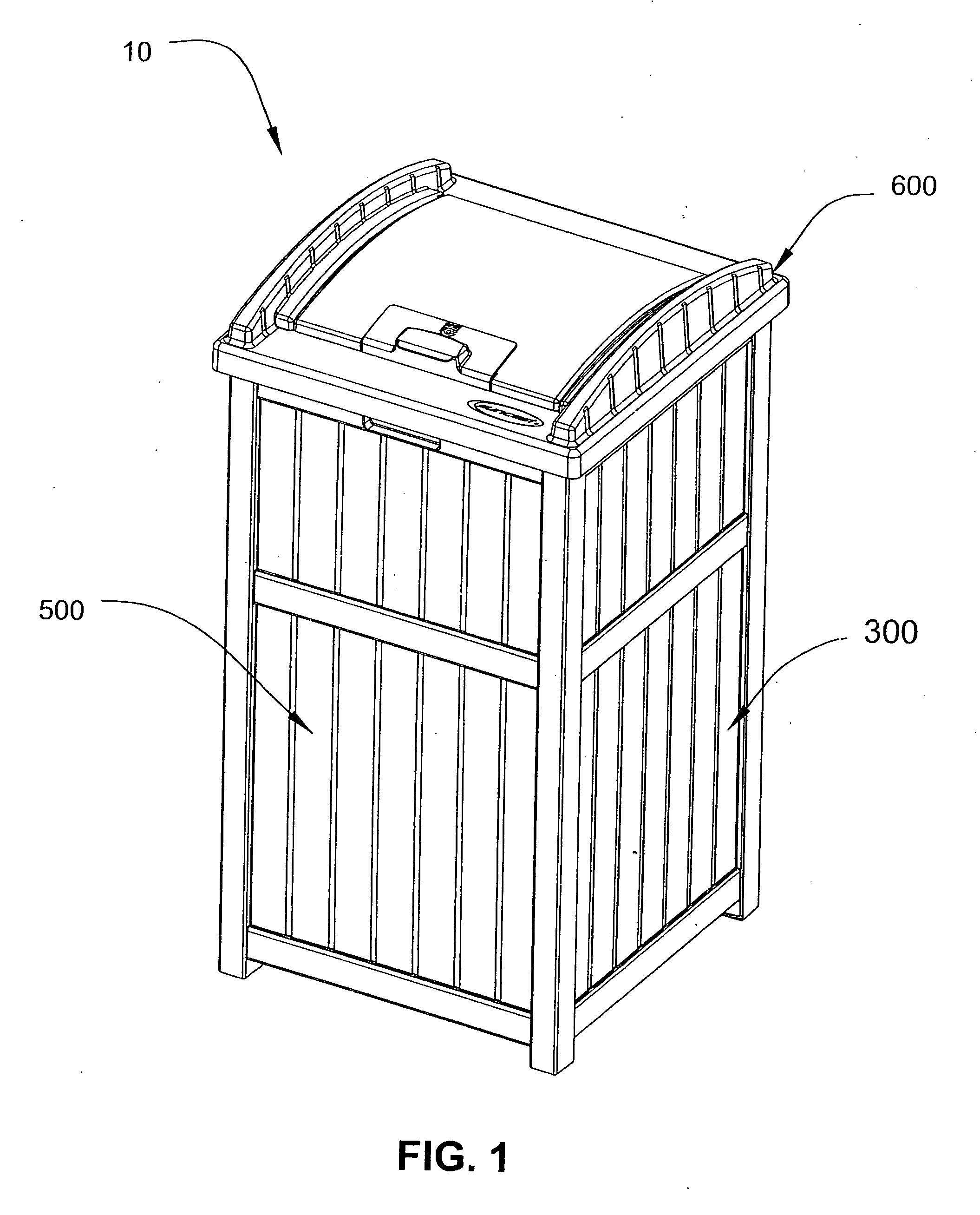
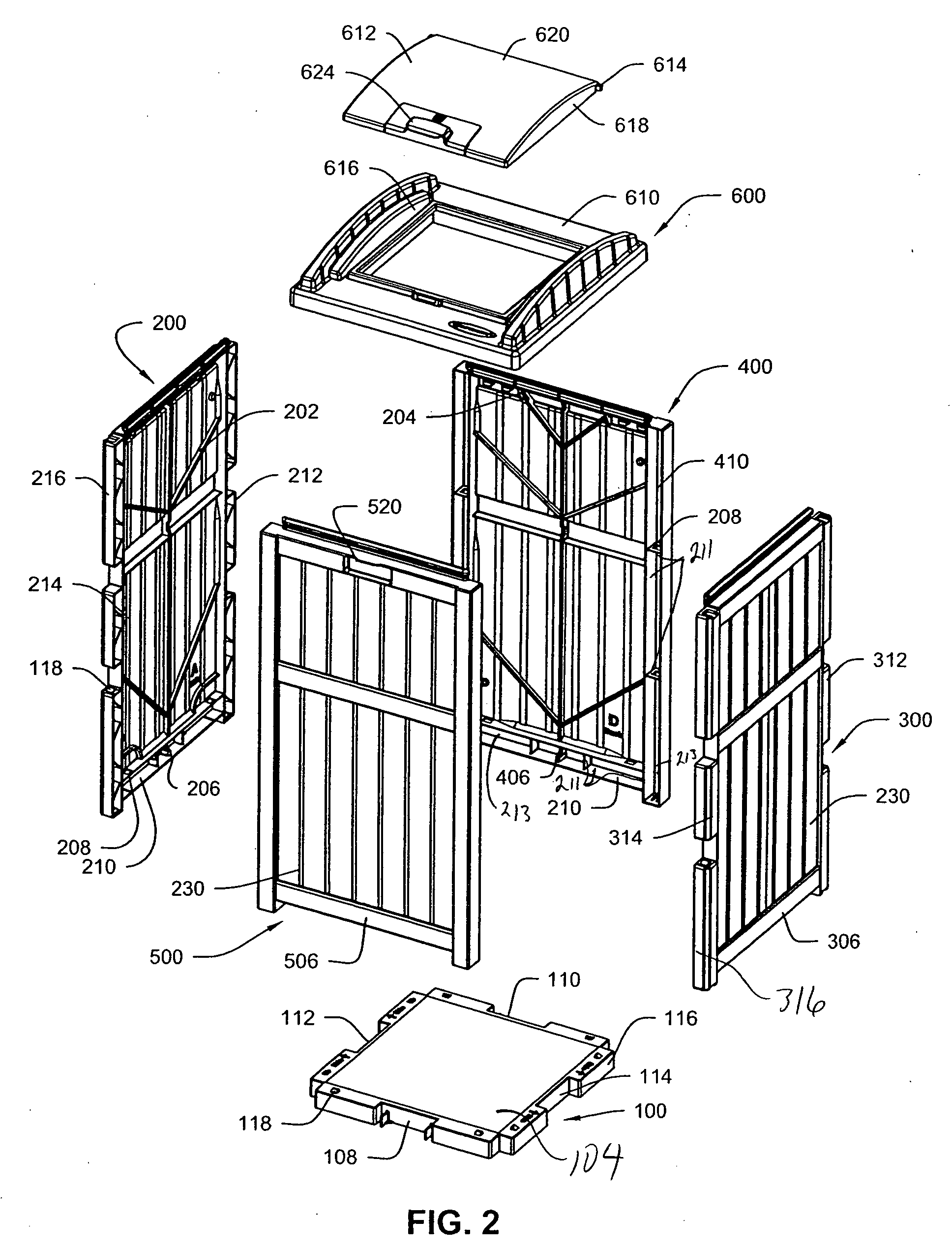
[0047]FIGS. 1-2 which are now referenced illustrate perspective and exploded views of the trash container assembly, generally referenced as 10, according to a preferred embodiment of the present invention. The trash container is made up of a floor panel 100, left side wall panel 200, right side wall panel 300, back wall panel 400, front wall panel 500 and cover panel 600. In the preferred embodiment, the panels comprising the assembly are formed of but not limited to a suitable plastic such as polystyrene or polyethylene, through the process of injection molding. The result is that the panels comprising the trash containe


PUM

PropertyMeasurementUnit
Perimeteraaaaaaaaaa

Abstract

The present invention provides a plurality of injection molded plastic panels having integrated connectors. The panels are constructed and arranged packaging and shipment in a nested and/or stacked arrangement. Thereafter, the panels may be assembled into a secure trash container. The integrally formed connectors of the side walls, cover and bottom panel components simplifies trash container construction by integrally forming the connectors into the injection molded panels which are snapped together. The panels are formed of injection molded plastic to interlock with one another without the need for separate metal fasteners or connectors.

Description


Claims


Application Information

Patent Timeline
Owner SUNCAST
Why Eureka
Try Eureka