Concentric Dual Drum Raster Scanning Beam System and Method

a dual-drum, raster scanning technology, applied in the field of penetrating radiation sources collimation, can solve the problems of cumbersome and cumbersome scanning of beams in more than a single dimension, extreme mass and ponderous, and high cos

Inactive Publication Date: 2007-07-26
AMERICAN SCI & ENG INC
View PDF3 Cites 25 Cited by
  • Summary
  • Abstract
  • Description
  • Claims
  • Application Information

AI Technical Summary

Benefits of technology

This patent describes a way to make sure that certain parts of an object are covered by different layers of material when it's being scanned. By controlling how fast each part moves during this process, we can create better quality images from these scans.

Problems solved by technology

The technical problem addressed in this patent is how to efficiently scan a beam of radiation with multiple dimensions while also being able to effectively block out any obstructions caused by the beam's movement.

Method used


Image

  • Concentric Dual Drum Raster Scanning Beam System and Method
  • Concentric Dual Drum Raster Scanning Beam System and Method
  • Concentric Dual Drum Raster Scanning Beam System and Method

Examples


Embodiment Construction

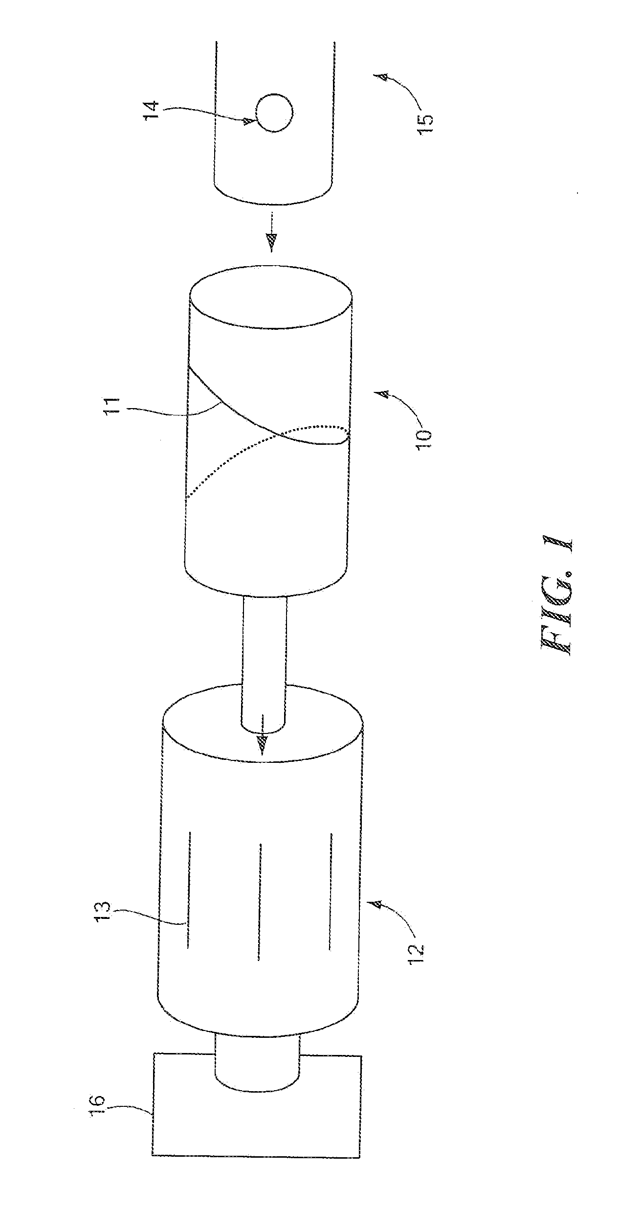
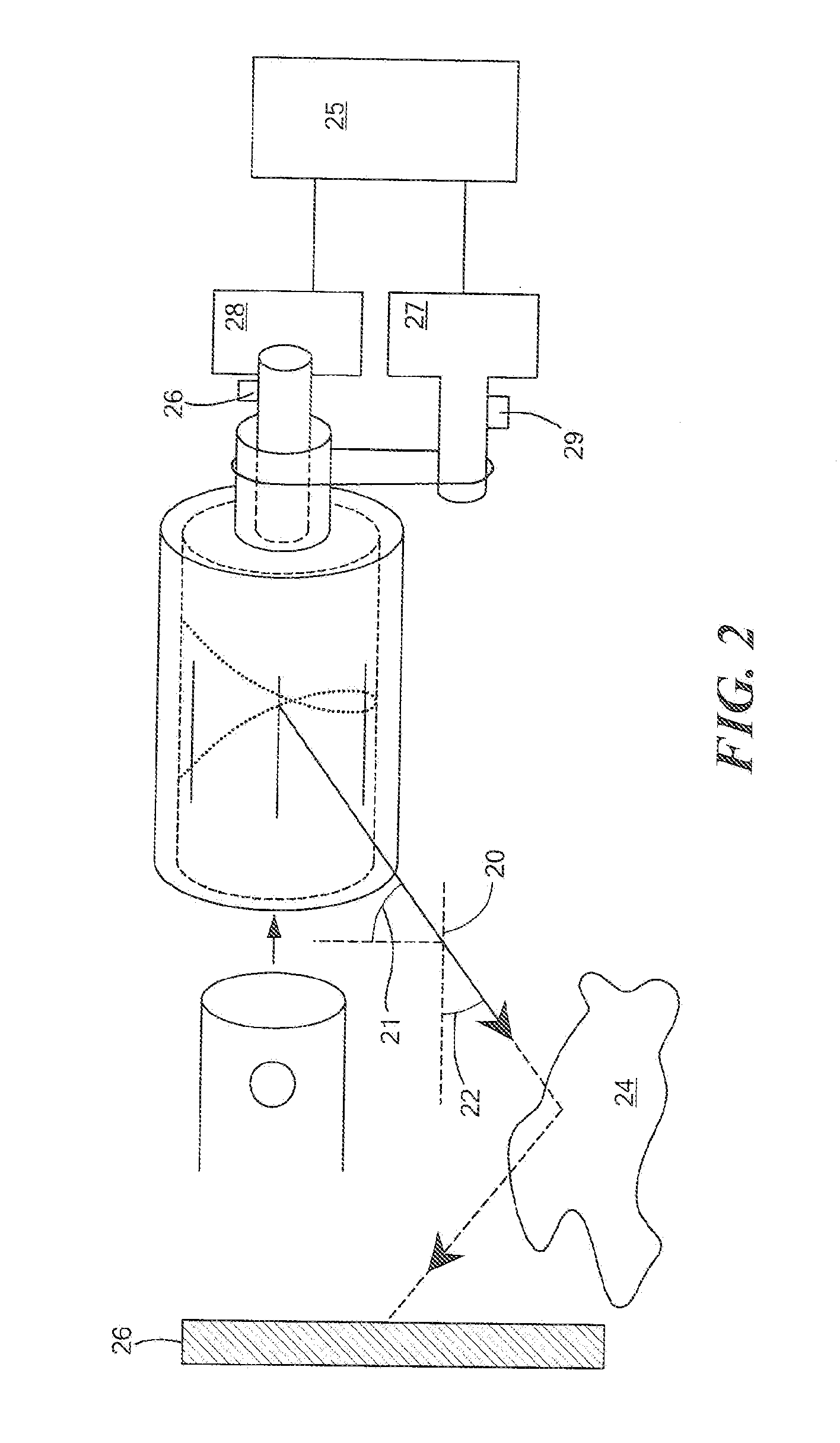
[0019] In accordance with preferred embodiments of the present invention, and as described with reference to FIG. 1, a cone of radiation, such as the x-ray cone produced by an x-ray source 14, may be collimated and scanned in two dimensions. Source 14 may be effective point source of radiation, including x-ray radiation. Cocentric cylindrical sleeves made of a material suitable for x-ray collimation (such as tungsten) are preferably used, as now described.

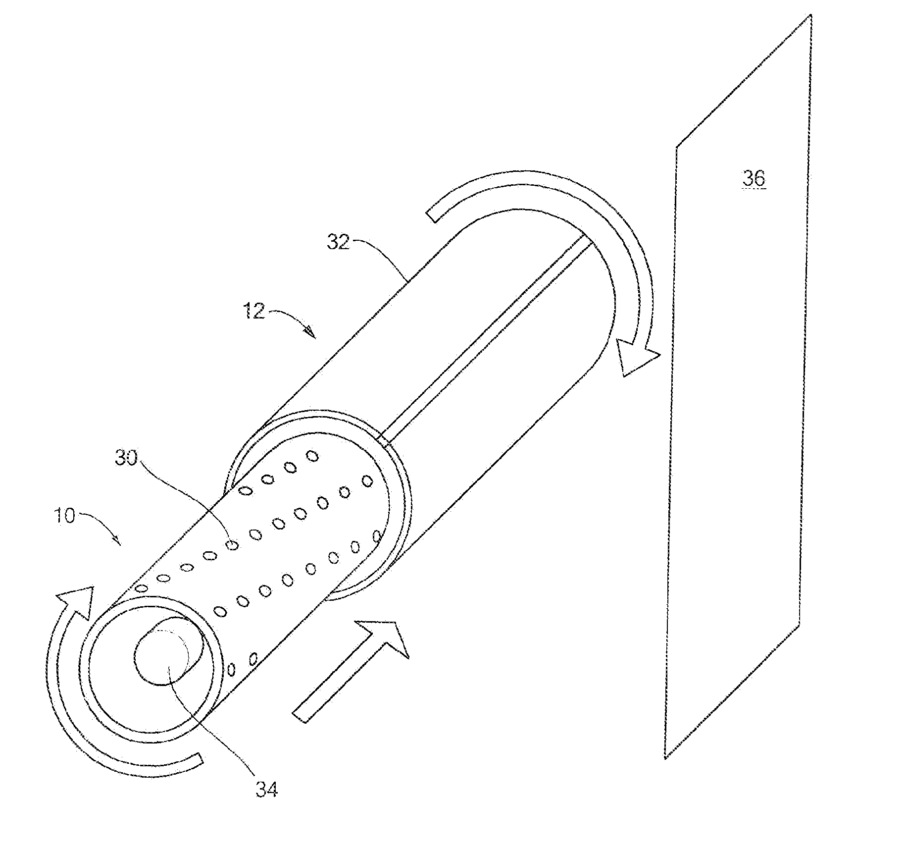
[0020] A first scanning element, such as inner sleeve 10, has helical slot 11 while a second scanning element, such as outer sleeve 12, has a horizontal slot 13. The end of a standard x-ray tube is shown as well. The respective slots provide for transmission of x-rays emitted from aperture 14 of x-ray source 15, typically an x-ray tube. One application of this invention is in the context of a portable machine capable of single-sided x-ray imaging of areas behind walls and the ceiling of a room. Inner 10 and outer 12 sleeves are rotat


PUM


Abstract

Devices and methods for collimation of a penetrating radiation source, such as an x-ray source, for the purpose of creating a scanning beam, as might be employed for purposes of imaging. A first scanning element, constrained to move about a first axis, has at least one aperture for scanning radiation from inside the first scanning element to outside the first scanning element. A second scanning element constrained to move with respect to a second axis, typically identical to the first, has at least one aperture for scanning radiation that has been transmitted through the first scanning element across a region of an inspected object.

Description


Claims


Application Information

Patent Timeline
Owner AMERICAN SCI & ENG INC
Why Eureka
Try Eureka