Locking speed driver

Inactive Publication Date: 2007-08-23
EMERSON ELECTRIC CO
View PDF16 Cites 1 Cited by
  • Summary
  • Abstract
  • Description
  • Claims
  • Application Information

AI Technical Summary

Benefits of technology

[0011] The present disclosure provides an improved system and method of using a speed driver with a shank that can be selectively locked to the handle. Such locking can occur without significant effort or even needing to remove the driver from the fastener during operation. The shank is biased in a first position for independent rotation in the handle, and in a second position selectively engaged with the handle. Thus, a locking speed driver can still offer the relatively rapid rotation from cranking the handle about the shank, yet selectively provide high torque similar to a fixed handle/shank arrangement in a typical screwdriver or other driver.

Problems solved by technology

However, such speed drivers are known for having typically little torque capabilities, because the offset distance is typically small due to other considerations such as storage and practical uses, and the handle freely rotates around the shank.

Method used


Image

  • Locking speed driver
  • Locking speed driver

Examples


Example

[0018] One or more illustrative embodiments incorporating the invention disclosed herein are presented below. Not all features of an actual implementation are described or shown in this application for the sake of clarity. It is understood that the development of an actual embodiment incorporating the present invention, numerous implementation-specific decisions must be made to achieve the developer's goals, such as compliance with system-related, business-related and other constraints, which vary by implementation and from time to time. While a developer's efforts might be complex and time-consuming, such efforts would be, nevertheless, a routine undertaking for those of ordinary skill in the art having benefit of this disclosure.

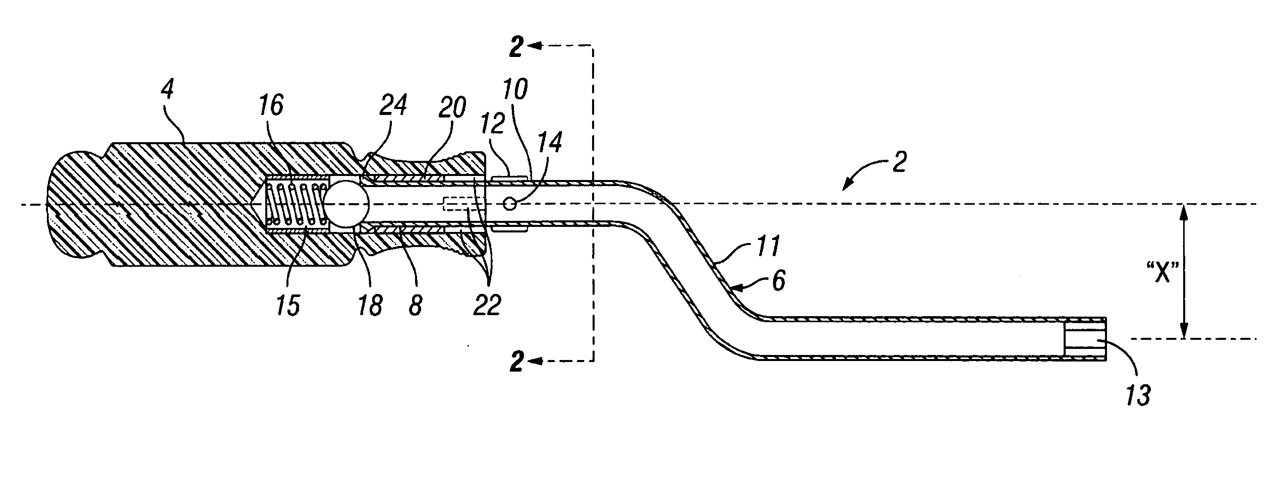
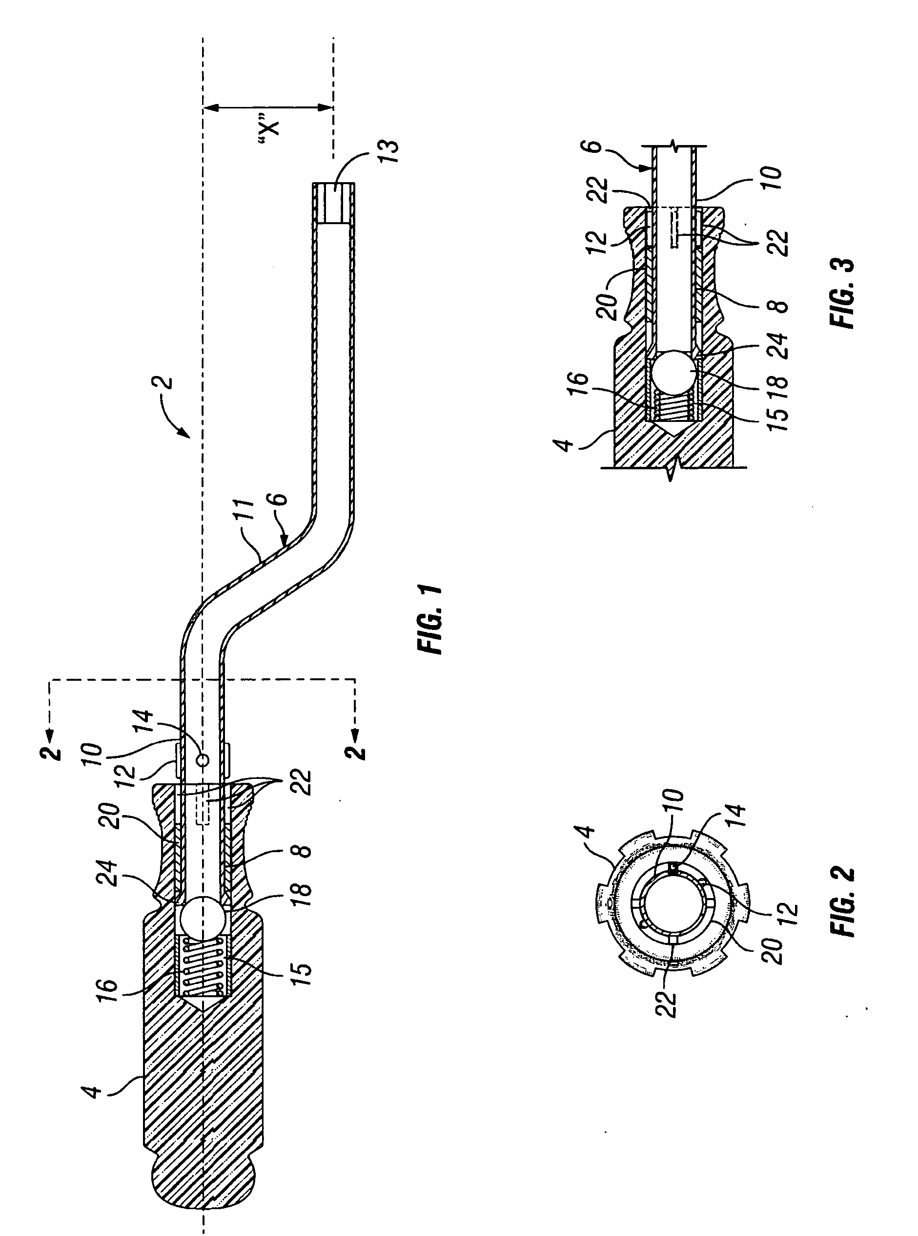
[0019]FIG. 1 is a schematic cross-sectional longitudinal view of an exemplary locking speed driver of the present disclosure. The locking speed driver generally includes a handle 4, and a shank 6 rotatably decoupled to the handle in a first mode, and rotatab


PUM


Abstract

The present disclosure provides an improved system and method of using a speed driver with a shank that can be selectively locked to the handle. Such locking can occur without significant effort or even removing the driver from the fastener during operation. The shank is biased in a first position with the handle for independent rotation in the handle, and selectively engaged with the handle in a second position with the handle. Thus, a speed driver can still offer the relatively rapid rotation from cranking the handle about the shank, yet selectively provide high torque similar to a fixed handle/shank arrangement in a typical screwdriver or other driver.

Description


Claims


Application Information

Patent Timeline
Owner EMERSON ELECTRIC CO
Why Eureka
Try Eureka