Transponder and method for a wireless data transmission

a wireless data and transponder technology, applied in the direction of burglar alarm mechanical actuation, burglar alarm by hand-portable object removal, instruments, etc., can solve the problems of substantially quality-dependent decline in the coil voltage and rapid decline, and achieve the effect of high transmission rang

Inactive Publication Date: 2007-08-23
ATMEL CORP
View PDF4 Cites 7 Cited by
  • Summary
  • Abstract
  • Description
  • Claims
  • Application Information

AI Technical Summary

Benefits of technology

The technical effect that this technology allows for better communication over longer distances without compromising on signal accuracy or reliability.

Problems solved by technology

The technical problem addressed in this patents relates to improving communication system performance without sacrificing energy resources due to high costs involved. Existing methods involve either increasing the number of times each transition requires another transactor or adding extra components such as filters. However these techniques may lead to decreased reliability if there were multiple transfers simultaneously being processed concurrently.

Method used


Image

  • Transponder and method for a wireless data transmission
  • Transponder and method for a wireless data transmission
  • Transponder and method for a wireless data transmission

Examples


Embodiment Construction

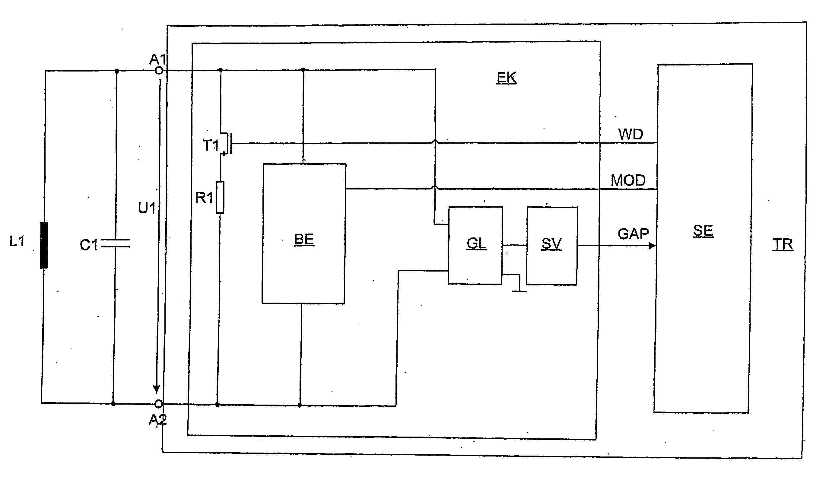
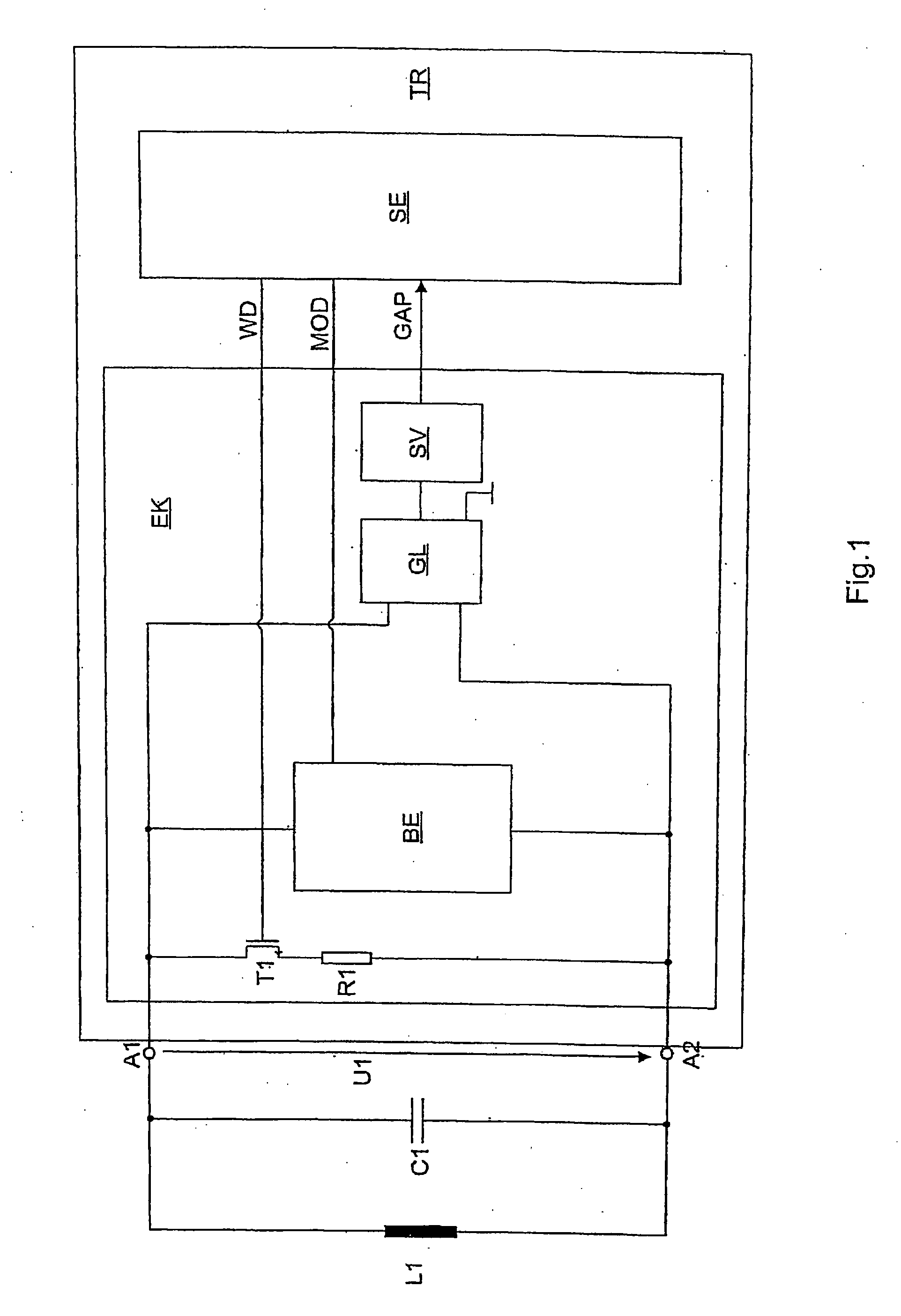
[0025]FIG. 1 shows a passive transponder TR in the form of an integrated circuit with an input circuit EK with input terminals A1 and A2 for connecting an antenna coil L1 for inductive coupling with a conventional base station (not shown).

[0026]A capacitor C1 is connected parallel to the antenna coil L1, whereby antenna coil L1 and capacitor C1 form a parallel resonant circuit whose resonance frequency is matched to a base station transmission frequency of 125 kHz. Antenna coil L1 forms a transformer coupling with an antenna coil (not shown) of the base station.

[0027]Input circuit EK of the transponder TR comprises a controllable voltage limiting unit BE as part of a modulation unit (not shown further), which is used for data transmission from transponder TR to base station by means of load modulation.

[0028]A switching element in the form of a MOS transistor T1 and a resistor R1 are looped serially between the input terminals A1 and A2 of the input circuit EK.

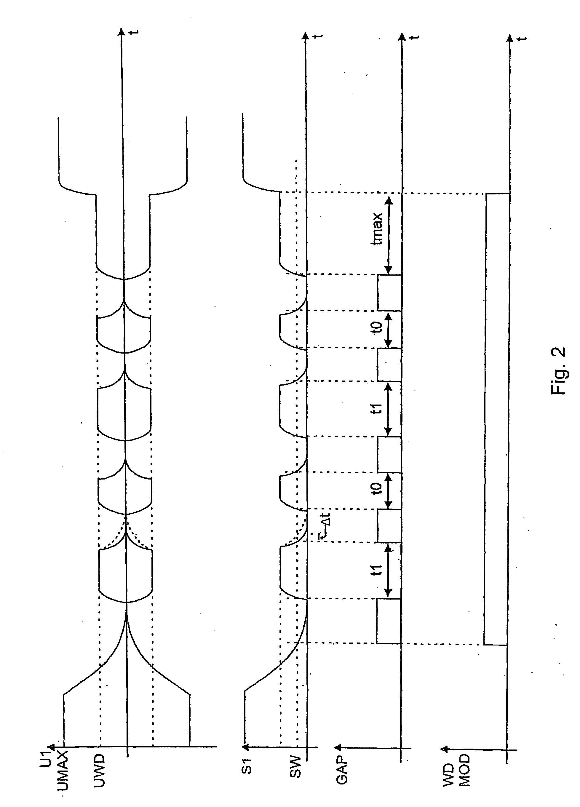
[0029]An alternating volta


PUM


Abstract

A transponder and a method for wireless data transmission is provided. The transponder comprises an input circuit with input terminals for connecting an antenna coil for data transmission to a base station by means of inductive coupling, a first controllable switching means, at least one resistor, which is looped in series with the first controllable switching means between the input terminals of the input circuit, and a controller which is designed in such a way that it connects through the first switching means as soon as a voltage applied at the input terminals falls below a first settable threshold value, and again interrupts it as soon as the voltage applied at the input terminals for a settable duration is above the first settable threshold value and/or above a second settable threshold value.

Description


Claims


Application Information

Patent Timeline
Owner ATMEL CORP
Why Eureka
Try Eureka