Ultrasonic scanning apparatus and method for diagnosing bladder

a scanning apparatus and ultrasonic technology, applied in ultrasonic/sonic/infrasonic diagnostics, instruments, applications, etc., can solve the problems of inconvenient use, inability to easily carry, and inability to accurately calculate the amount of urine in the bladder, so as to minimize user interference and accurate calculation

Inactive Publication Date: 2007-08-23
MCUBETECH
View PDF4 Cites 5 Cited by
  • Summary
  • Abstract
  • Description
  • Claims
  • Application Information

AI Technical Summary

Benefits of technology

The technical effect that this inventor solves by providing an improved device called Ultrasound Scan (US) with features like accuracy at calculating how much liquid needs being excreted from your body without getting too close or interacting yourself with things around them.

Problems solved by technology

The technical problem addressed by this patented technology relating to improving the convenience and usability of electronic devices such as smartphones with built-in cameras (ultrasonics) can include how easy carrying them around without being bulky and overweighting themselves. Existing solutions involve either having multiple separate components attached at once or requiring complicated calculations involving both the acquisition process itself and the measurement processes.

Method used


Image

  • Ultrasonic scanning apparatus and method for diagnosing bladder
  • Ultrasonic scanning apparatus and method for diagnosing bladder
  • Ultrasonic scanning apparatus and method for diagnosing bladder

Examples


Embodiment Construction

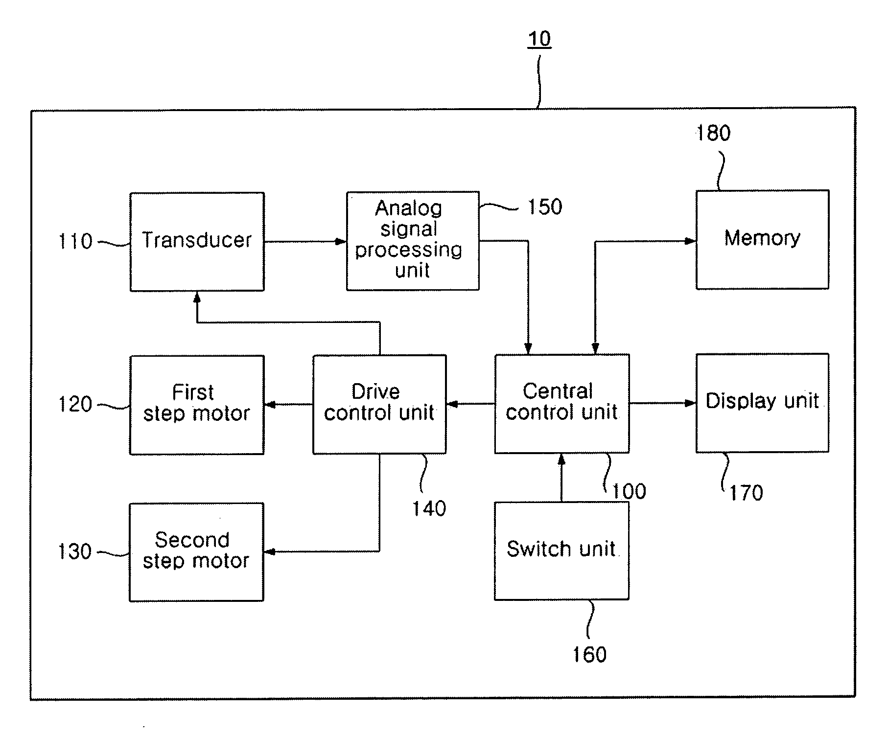
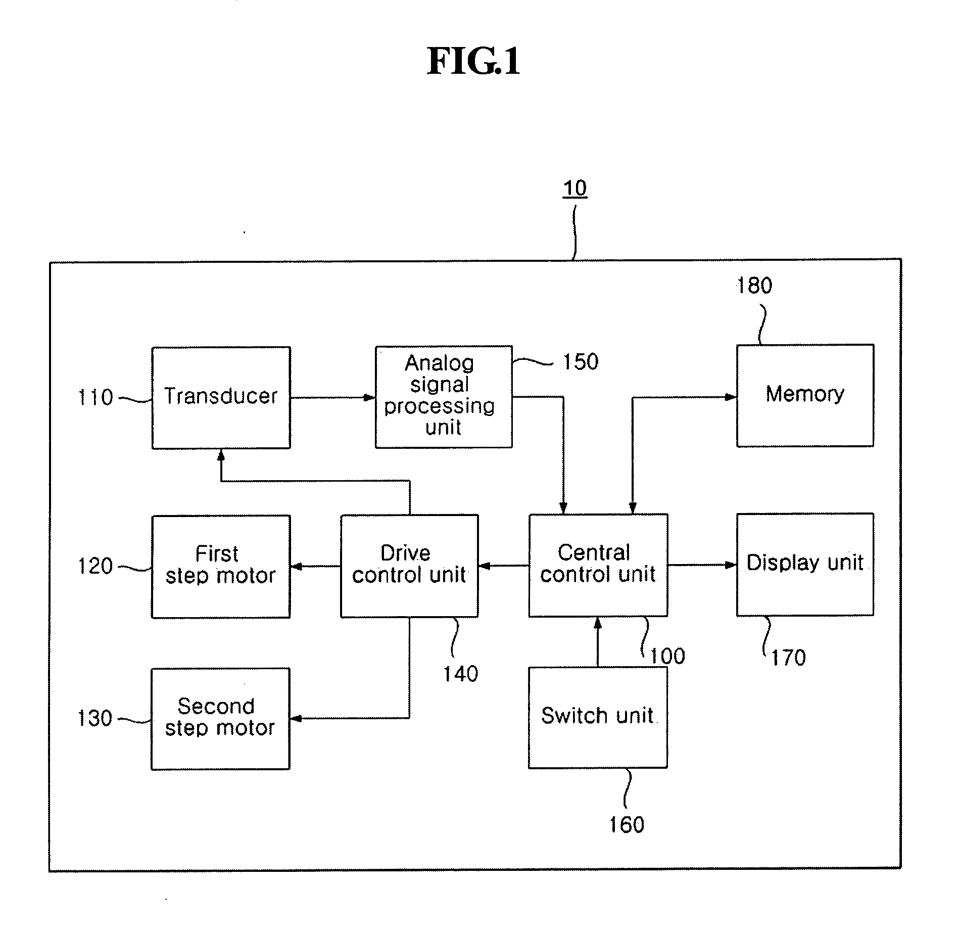
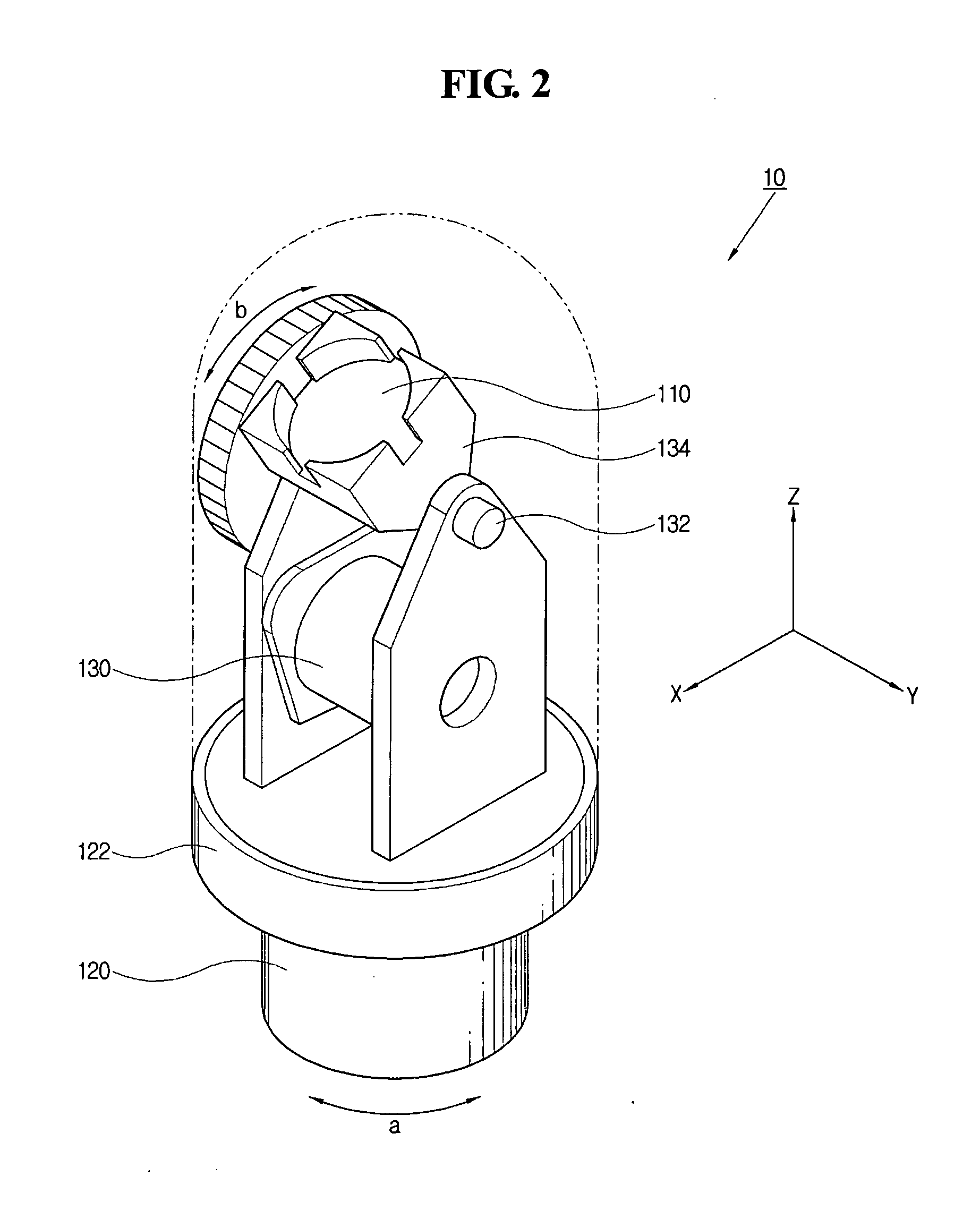
[0022] The construction and operation of an ultrasonic scanning apparatus for diagnosing a bladder according to a preferred embodiment of the present invention are described in detail with reference to the accompanying drawings. FIG. 1 is a block diagram schematically showing the internal construction of an ultrasonic scanning apparatus according to a preferred embodiment of the present invention, and FIG. 2 is a perspective view showing the ultrasonic scanning apparatus of FIG. 1.

[0023] Referring to FIG. 1, the ultrasonic scanning apparatus 10 according to the preferred embodiment of the present invention includes a central control unit 100 for controlling the overall operation of the apparatus, a transducer 110, a first stepping motor 120, a second stepping motor 130, a drive control unit 140, an analog signal processing unit 150, a switch unit 160, memory 180, and a display unit 170. The respective components of the above-described ultrasonic scanning apparatus 10 are described in


PUM


Abstract

Disclosed herein is ultrasonic scanning apparatus and method for diagnosing a bladder. The ultrasonic scanning apparatus includes a transducer, a transducer support, an analog signal processing unit, a display unit, a central control unit, a first stepping motor, a second stepping motor, and a drive control unit. The transducer emits ultrasonic signals for respective scan lines and receives ultrasonic signals reflected from an object. The transducer support configured such that the transducer is fixedly installed therein. The analog signal processing unit converts the ultrasonic signals into digital signals. The display unit outputs specific image signals. The central control unit performs image processing on the digital ultrasonic signals, outputs the results of the processing to the display unit, and controls the overall operation of the apparatus. The first stepping motor rotates in a first direction. The second stepping motor rotates in a second direction. The drive control unit controls the operation of the first and second stepping motors in response to drive control signals provided from the central control unit.

Description


Claims


Application Information

Patent Timeline
Owner MCUBETECH
Why Eureka
Try Eureka